
Measuring device and die core processing method using same

A measuring device and a mold core processing technology, applied in metal processing equipment, measuring/indicating equipment, metal processing machinery parts, etc., can solve problems such as damage, laser processing machine crashes, laser processor falling height and impact on mold cores, etc. , to achieve the effect of ensuring the machining accuracy

Inactive Publication Date: 2014-08-06
HONG FU JIN PRECISION IND (SHENZHEN) CO LTD +1
View PDF0 Cites 3 Cited by
  • Summary
  • Abstract
  • Description
  • Claims
  • Application Information

AI Technical Summary

Problems solved by technology

[0003] However, there are many light guide plates of different specifications on the production line and mold cores of different heights are used. Operators often mistake the height of the mold core, causing the laser processor to drop too much and hit the mold core, causing the laser processing machine to crash or even be damaged.

Method used


Image

  • Measuring device and die core processing method using same
  • Measuring device and die core processing method using same

Examples


Embodiment Construction

[0013] The embodiments of the present invention will be further described in detail below in conjunction with the accompanying drawings.

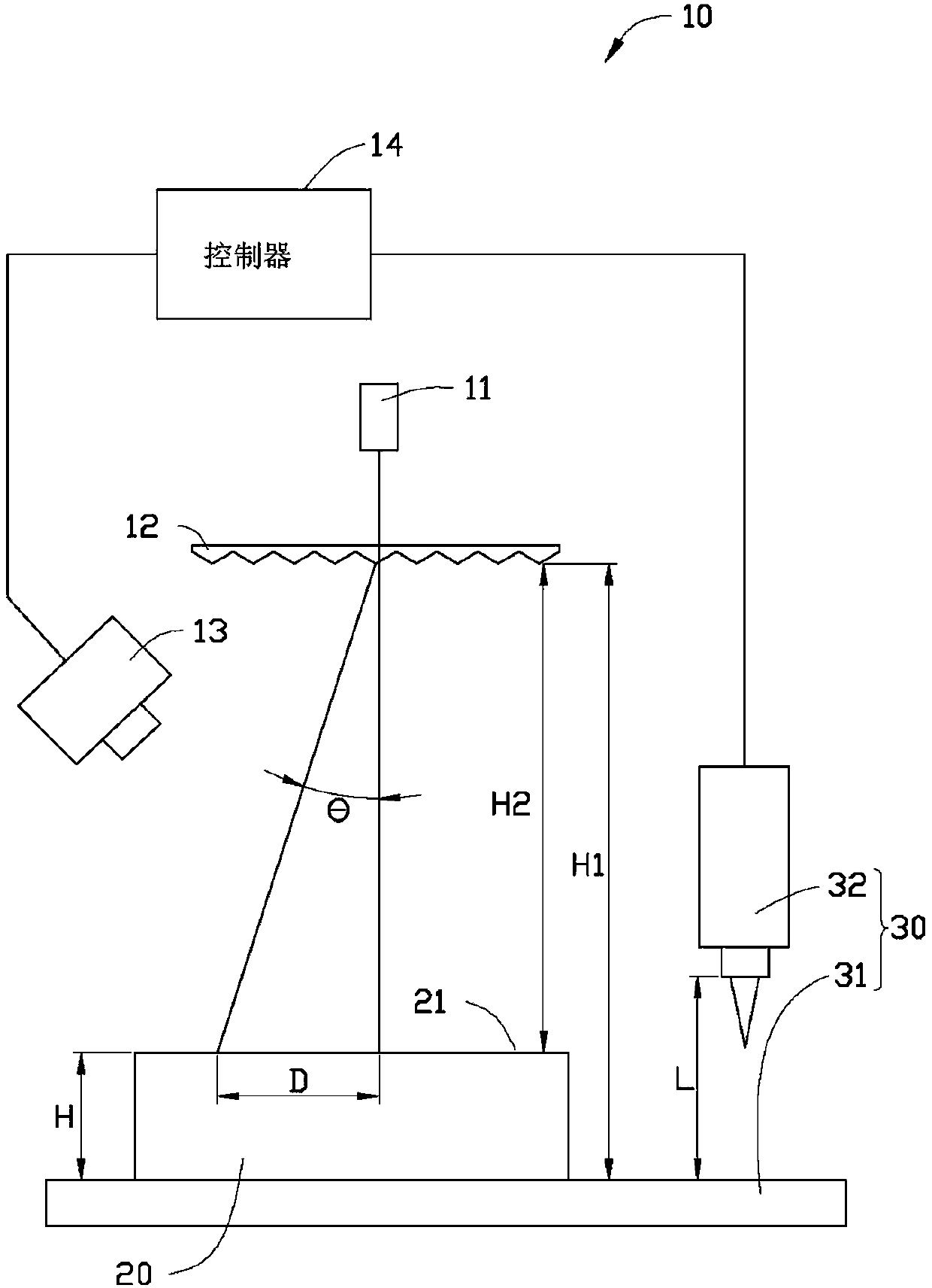
[0014] see figure 1 , the measuring device 10 of the present invention is used to measure the height of a mold kernel 20 before processing. The measuring device 10 is arranged above a laser processing machine 30 . The laser processing machine 30 includes a machine table 31 and a laser processing device 32 . The mold core 20 is carried on the machine table 31 .

[0015] The measuring device 10 includes a laser generator 11 , a grating 12 , a camera 13 and a controller 14 .

[0016] The laser generator 11 is fixed above the mold core 20 , and the laser emitted by it is perpendicular to an upper surface 21 of the mold core 20 .

[0017] The grating 12 is fixed between the laser generator 11 and the mold core 20, and the grating 12 is used to divide the laser light emitted by the laser generator 11 into two beams with a predetermined angle ...


PUM


Abstract

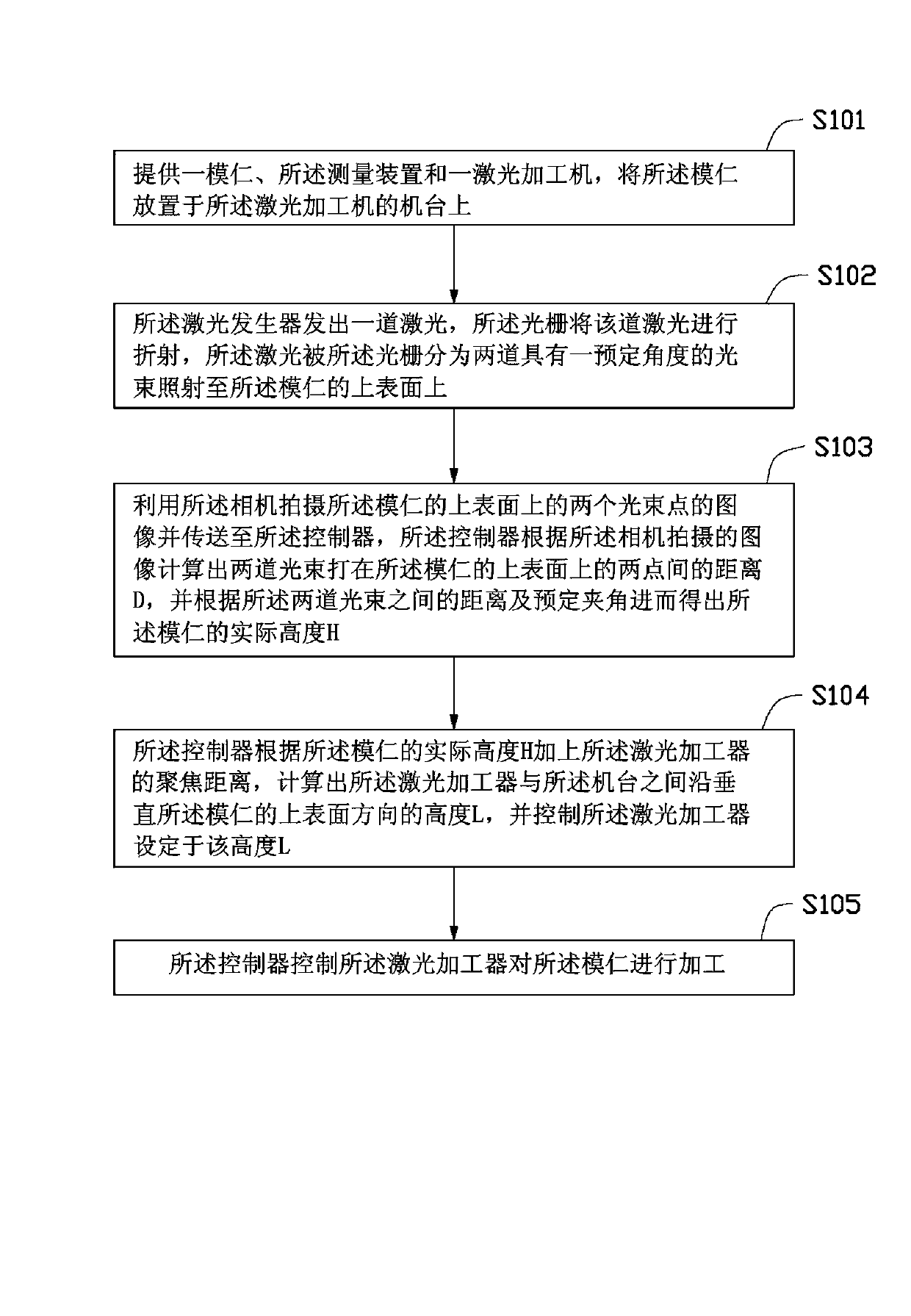
The invention relates to a measuring device used for measuring height of a die core before processing. The measuring device comprises a laser generator, a raster, a camera and a controller. The laser generator is fixedly arranged above the die core, laser light emitted by the laser generator is perpendicular to the upper surface of the die core. The raster is fixedly arranged between the laser generator and the die core and used for dividing the laser light emitted by the laser generator into two channels of light beams with a preset included angle to irradiate the upper surface of the die core. The camera is arranged above the die core and used for taking pictures of the upper surface of the die core. The controller is electrically connected with the camera, receives images taken by the camera and calculates practical height of the die core. The invention further relates to a die core processing method using the measuring device.

Description

technical field [0001] The invention relates to a measuring device and a mold core processing method using the measuring device. Background technique [0002] When the dot core of the light guide plate for injection is processed by a laser processing machine, the laser processing machine moves to a fixed height above the mold core. This height is the focus height of the laser pulse light of the laser processing machine. The focus height depends on different processing demand setting. When operating the laser processing machine to process the dots, the height of the mold core must be manually input. At this time, the laser processor should automatically move to a specific height from the machine. The specific height is equal to the height of the mold core plus the focus height, so that the laser focus point is located at Kernel surface for processing. [0003] However, there are many light guide plates of different specifications on the production line and mold cores of dif...

Claims


Application Information

Patent Timeline
Patent Type & Authority Applications(China)
IPC IPC(8): B23K26/03B23K26/00
CPCB23Q17/20B23Q17/2409B23Q17/2471
Inventor 曾永昌
Owner HONG FU JIN PRECISION IND (SHENZHEN) CO LTD
Learn More