
A gas-propelled underground fluid layered sampling device

A technology for underground fluids and sampling devices, applied in wellbore/well components, earth-moving drilling, etc., can solve the problem that the change of particle concentration of formation fluid cannot be reflected in real time, the air cannot be removed from the wellbore with structural design, and the formation fluid cannot be continuously entered, etc. problems, to achieve good application prospects and commercial value, simple and convenient installation and sampling operations, ingenious and novel structure

Active Publication Date: 2017-05-17
INST OF ROCK & SOIL MECHANICS CHINESE ACAD OF SCI
View PDF6 Cites 2 Cited by
  • Summary
  • Abstract
  • Description
  • Claims
  • Application Information

AI Technical Summary

Problems solved by technology

However, there are still some technical difficulties, such as the clogging of small holes caused by sediment particles or freezing in winter, which leads to the failure of the sampling system; the structural design makes the original air in the wellbore unable to be removed, resulting in premature balance between the internal overpressure air and the external water head pressure difference, As a result, the formation fluid cannot continue to enter the sampling system; interlayer water or long-term residual fluid in the wellbore causes the samples taken on the ground to lose representativeness, that is, it cannot reflect the changes in the particle concentration of the specified formation fluid in real time, which greatly reduces the quality of the sample

Method used


Image

  • A gas-propelled underground fluid layered sampling device
  • A gas-propelled underground fluid layered sampling device
  • A gas-propelled underground fluid layered sampling device

Examples


Embodiment 1

[0110] Below in conjunction with accompanying drawing, the present invention is described in further detail:

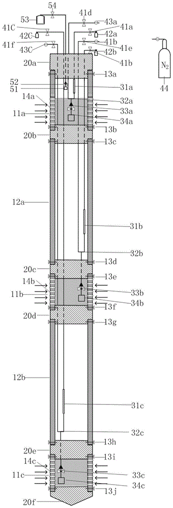
[0111] according to figure 1 It can be seen that a gas-propelled subsurface fluid stratified sampling device includes a wellbore system 10, a simple packer system 20, a U-tube underground liquid sampling system 30, a gas-propelled surface liquid sampling system 40 and a soil gas sampling system. 50.

[0112] The functions and connection methods of each system are described as follows: the port of the simple packer system 20 is inserted into the pipe of the wellbore system 10, and is inserted through the first layer of screws 13a, the second layer of screws 13b, the third layer of screws 13c, and the fourth layer of screws 13d. , The fifth layer of screws 13e, the sixth layer of screws 13f, the seventh layer of screws 13g, the eighth layer of screws 13h, the ninth layer of screws 13i, and the tenth layer of screws 13j are firmly riveted to form a whole with an outer ...


PUM


Abstract

The invention discloses a gas pushing type underground fluid stratified sampling device. The end port of a simple packer system is inserted into a pipe of a shaft system to perform embedding and fixedly riveted with the pipe through screws to form an integral cylindrical structure. The integral cylindrical structure is buried in the stratum through drilled holes, and a guide pipe in the integral cylindrical structure penetrates through small holes preserved in simple packers to be connected with a U-shaped pipe underground fluid sample feeding system. The guide pipe penetrates through the small hole preserved in a first simple packer to be connected with a gas phase filter and a gas phase check valve of a soil gas sampling system and penetrates through the first simple packer to be connected with a needle valve on the ground and a fluid sampling container. A gas pushing type ground fluid sampling system penetrates through the small hole preserved in the first simple packer to be connected with the U-shaped underground fluid sample feeding system. The gas pushing type underground fluid stratified sampling device is ingenious and novel in structure, low in cost, excellent in durability, strong in field adaptability, wide in application fields, strong in project demands and good in application prospect and commercial value.

Description

technical field [0001] The invention relates to the field of subsurface fluid sampling in shallow formations, and more particularly relates to a device for sampling groundwater and soil gas layers in shallow wells based on the principle of gas push. Background technique [0002] Subsurface fluid is an important factor related to the evolution of the earth and the survival of surface organisms. Subsurface fluid sampling can continuously provide a large amount of physical, chemical and microbial information about the formation through isotope tracking, formation residual gas analysis, chemical composition testing, microbial community characteristics and other analysis methods, which is of great guiding significance for engineering development and environmental safety assessment One of the means of monitoring. [0003] To analyze subsurface fluids, a subsurface fluid sample must first be obtained. According to the classification of working principles, various subsurface fluid...

Claims


Application Information

Patent Timeline
Patent Type & Authority Patents(China)
IPC IPC(8): E21B49/08
Inventor 李小春刘学浩李琦方志明
Owner INST OF ROCK & SOIL MECHANICS CHINESE ACAD OF SCI
Learn More