Air compressor centrifugal impeller

A technology of aero-engines and centrifugal impellers, which is applied in the direction of machines/engines, liquid fuel engines, mechanical equipment, etc. It can solve the problems of short service life of the wheel disc, failure to meet the strength requirements, and increased self-weight of the impeller, so as to improve the bearing capacity and reduce the weight of the impeller. Influence of structure, effect of weight reduction

Active Publication Date: 2017-01-25
CHINA AVIATION POWER MACHINE INST
View PDF6 Cites 2 Cited by
  • Summary
  • Abstract
  • Description
  • Claims
  • Application Information

AI Technical Summary

Problems solved by technology

[0004] The purpose of the present invention is to provide a compressor centrifugal impeller of an aero-engine, so as to solve the problem that the existing impeller disc completely depends on the increase of the structural thickness of the impeller to improve the bearing capacity of the impeller disc, resulting in an increase in the self-weight of the impeller while still failing to meet the strength requirements. Technical problems causing a short service life of the roulette

Method used


Image

  • Air compressor centrifugal impeller
  • Air compressor centrifugal impeller
  • Air compressor centrifugal impeller

Examples


Embodiment Construction

[0027] The embodiments of the present invention will be described in detail below with reference to the accompanying drawings, but the present invention can be implemented in various ways defined and covered.

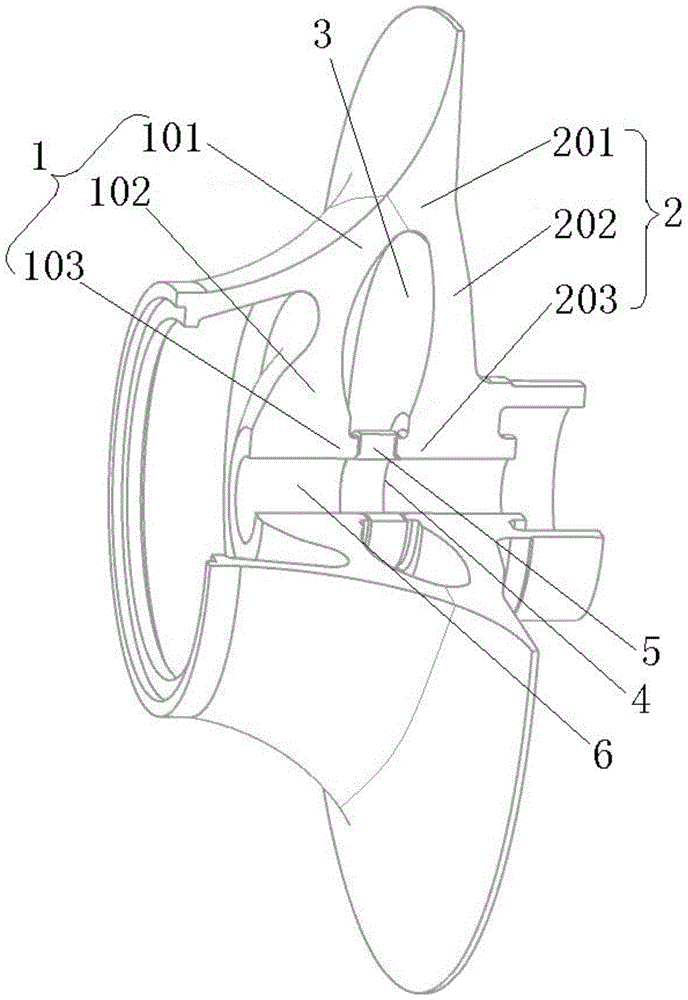
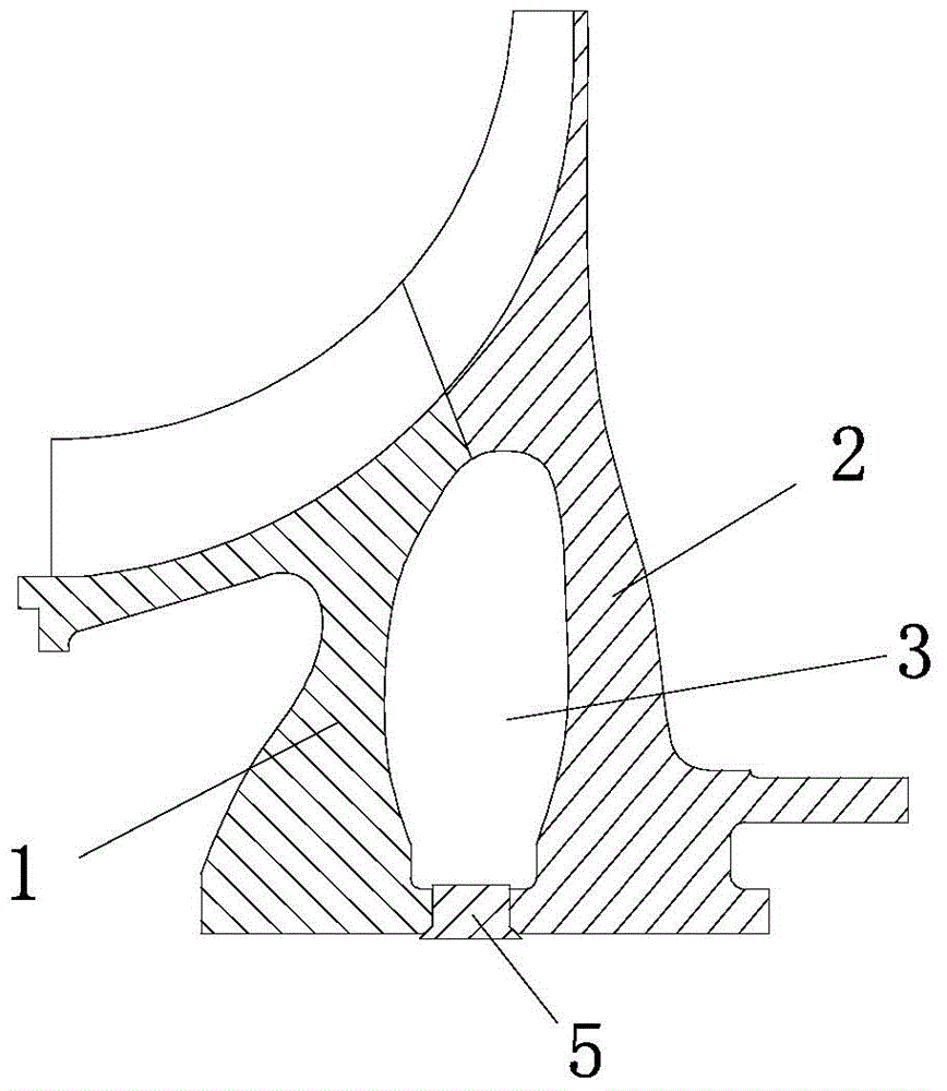
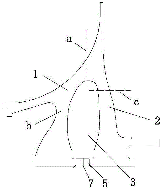
[0028] figure 1 It is a structural schematic diagram of the centrifugal impeller of the compressor of the aero-engine of the preferred embodiment of the present invention; figure 2 It is a schematic cross-sectional structure diagram of a centrifugal impeller of a compressor in a preferred embodiment of the present invention; image 3 It is a schematic diagram of the welded structure of the centrifugal impeller of the compressor in the preferred embodiment of the present invention; Figure 4 It is a schematic diagram of the assembly structure of the spacer ring in the preferred embodiment of the present invention; Figure 5 It is a schematic diagram of the stress distribution of the centrifugal impeller of the compressor of the aero-engine.

[0029] Such as figure 1...


PUM


Abstract

The invention discloses a compressor centrifugal vane wheel of an aircraft engine. The compressor centrifugal vane wheel comprises a first disc and a second disc. The first disc and the second disc are overlapped to form the integral vane wheel. The first disc comprises a first outer ring edge, a first ring body and a first inner ring edge. The first outer ring edge is arranged at the outer edge of the first ring body and the first inner ring edge is arranged at the inner edge of the first ring body. The second disc comprises a second outer ring edge, a second ring body and a second inner ring edge. The second outer ring edge is arranged at the outer edge of the second ring body and the second inner ring is arranged at the inner edge of the second ring body. An inner cavity is defined by the first outer ring edge, the first ring body, the first inner ring edge, the second outer ring edge, the second ring body and the second inner ring edge in an enclosed mode and used for reducing the dead load of a low-stress zone structure. A limiting structure used for keeping the relative spacing distance between the first inner ring edge and the second inner ring edge is arranged between the first inner ring edge and the second inner ring edge. The weight of an impeller disc can be effectively reduced, the stress of the impeller disc is reduced, the service life of the impeller disc is prolonged, the axial movement of an outlet of the centrifugal impeller can be reduced due to a double-channel load-carrying structure, and the design of gaps between blade bits is facilitated.

Description

technical field [0001] The invention relates to the field of aero-engines, in particular to a compressor centrifugal impeller of an aero-engine. Background technique [0002] Aeroengines or other gas turbine engines mainly rely on the compressor to deliver high-pressure airflow to the combustion chamber to realize the fuel injection and ignition of the combustion chamber and generate high-temperature and high-pressure gas. The centrifugal impeller of the compressor is the main part of the compressor. Through the impeller blades The rotation does work on the airflow, increasing the pressure and temperature of the airflow. [0003] Most of the discs of the existing impellers are of an integral structure, namely the so-called single disc structure. As the rotating speed of the disc increases or the radius of the impeller increases, the centrifugal load on the impeller increases. At this time, the disc needs to add more material to bear the load, thus increasing the weight of t...

Claims


Application Information

Patent Timeline
Patent Type & Authority Patents(China)
IPC IPC(8): F04D29/28
Inventor 蔡显新齐思鑫吴某斌
Owner CHINA AVIATION POWER MACHINE INST
Why Eureka
Try Eureka