Hydraulic oil tank for hydraulic system

A hydraulic oil tank and hydraulic system technology, which is applied in the direction of fluid pressure actuation system components, oil supply tank devices, fluid pressure actuation devices, etc., can solve the problems of short service life and poor effect, and achieve purity assurance, convenient use, The effect of simple structure

Inactive Publication Date: 2014-08-06
XINXIELI PRESS PLATE
View PDF2 Cites 2 Cited by
  • Summary
  • Abstract
  • Description
  • Claims
  • Application Information

AI Technical Summary

Problems solved by technology

[0003] In order to solve the problems of short service life and poor effect of existing common hydraulic oil tanks, the present invention provides the following technical solutions:

Method used


Image

  • Hydraulic oil tank for hydraulic system

Examples


Embodiment Construction

[0020] The preferred embodiments of the present invention will be described in detail below in conjunction with the accompanying drawings, so that the advantages and features of the present invention can be more easily understood by those skilled in the art, so as to define the protection scope of the present invention more clearly.

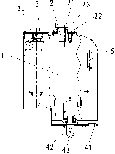
[0021] as attached figure 1 As shown in the schematic diagram of the structure of the present invention, a hydraulic oil tank for a hydraulic system includes a tank 1, a fuel filler 2 fixed on the upper part of the tank 1, an oil return filter element 3 installed on one side of the tank 1, The screw plug 41 installed on the bottom of one side of the box body 1 and the oil suction joint 42 installed on the bottom of the box body 1 and located on one side of the screw plug 41, the oil filler port 2 is equipped with a filler filter 21. A fuel filler flange 22 is fixedly installed on the outside of the filler port 2, and a flange 31 is installed...


PUM


Abstract

The invention provides a hydraulic oil tank for a hydraulic system. The hydraulic oil tank for the hydraulic system comprises a tank body, an oil filling opening fixedly formed in the upper portion of the tank body, an oil return filter element installed on one side of the tank body, a screw plug installed at the bottom of one side of the tank body, and an oil sucking connector installed at the bottom of the tank body and located on one side of the screw plug, wherein the oil filling opening is provided with an oil filling filter, an oil filling flange is fixedly installed outside the oil filling opening, and a flange is installed on the portion, located on the outer side of the oil return filter element, of the tank boy. The hydraulic oil tank for the hydraulic system has the advantages of being simple in structure and convenient to use, the oil filling filter and the oil return filter element are installed through a refilling opening and an oil return opening respectively, the purity of hydraulic oil is guaranteed, and therefore the long-time using effect of the hydraulic oil is guaranteed, and it is guaranteed that in the moving process, enough hydraulic driving force is provided for mechanical parts.

Description

technical field [0001] The invention relates to the field of mechanical equipment, in particular to a hydraulic oil tank used in a hydraulic system for driving mechanical equipment. Background technique [0002] There are many kinds of mechanical equipment. When the mechanical equipment is running, some of its parts and even itself can perform different forms of mechanical movement. Mechanical equipment consists of driving device, transmission device, transmission device, working device, braking device, protection device, lubrication system, cooling system and other parts. The driving device includes motor, air cylinder, hydraulic cylinder and so on. The drive of the existing hydraulic cylinder is usually composed of a fuel tank fuel pump, but there is no filter device in the fuel tank, which makes the existing hydraulic oil tank have a short service life, low efficiency, and poor effect. After a period of time, the driving force of the hydraulic oil will produce a certain ...

Claims


Application Information

Patent Timeline
Patent Type & Authority Applications(China)
IPC IPC(8): F15B1/26F15B21/04
Inventor 梁爱军
Owner XINXIELI PRESS PLATE
Why Eureka
Try Eureka