Torque shunting transmission mechanism for helicopter main reducing gear

A main reducer and split torsion transmission technology, which is applied in the direction of motor vehicles, transmission devices, gear transmission devices, etc., can solve the problems of complex installation, increase the force of cylindrical gears, and reduce fatigue life, so as to achieve uniform power distribution and improve load bearing The effect of strong capacity and carrying capacity

Active Publication Date: 2014-08-06
NORTHWESTERN POLYTECHNICAL UNIV
View PDF10 Cites 23 Cited by
  • Summary
  • Abstract
  • Description
  • Claims
  • Application Information

AI Technical Summary

Problems solved by technology

In the two-branch transmission mechanism, one cylindrical gear meshes with the upper and lower face gears, the ...

Method used


Image

  • Torque shunting transmission mechanism for helicopter main reducing gear
  • Torque shunting transmission mechanism for helicopter main reducing gear

Examples


Embodiment 1

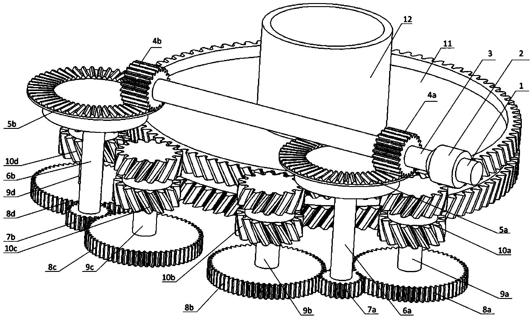
[0018] Such as figure 1 As shown, the single engine input split torque transmission mechanism in this embodiment includes a first engine output shaft 1 , and the first engine output shaft 1 is connected to the first power input shaft 3 through a first overrunning clutch 2 . The first spur gear 4a and the second spur gear 4b are installed on the first power input shaft 3; the first spur gear 4a meshes with the first face gear 5a, and the first face gear 5a passes through the first pair The joint gear shaft 6a is connected with the third spur gear 7a; the second spur gear 4b is meshed with the second face gear 5b, and the second face gear 5b is connected to the fourth spur gear through the second double gear shaft 6b. The gears 7b are connected to each other; the third spur gear 7a meshes with the fifth spur gear 8a and the sixth spur gear 8b, and the fifth spur gear 8a is connected to the first spur gear through the third double gear shaft 9a. The spur gears 10a are connected ...

Embodiment 2

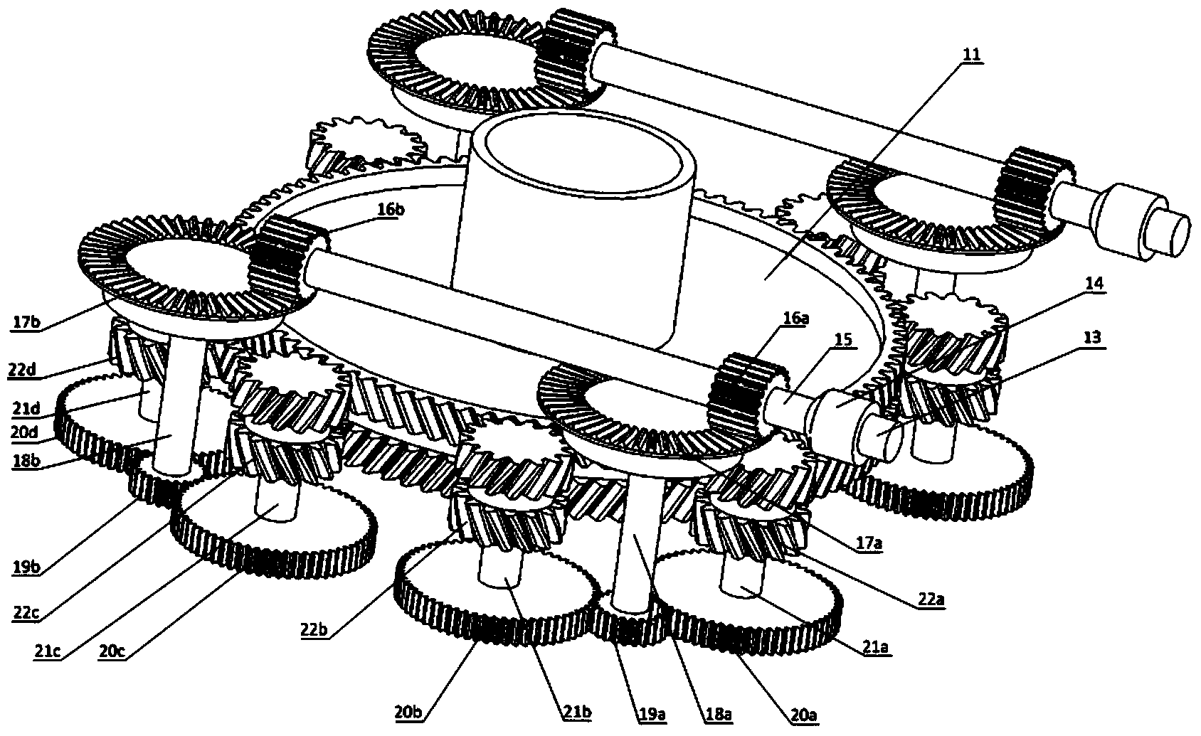
[0021] Such as figure 2As shown, the dual-engine input split-torque transmission mechanism in this embodiment is based on the single-engine input split-torque transmission mechanism by adding the second engine output shaft 13, the second overrunning clutch 14, the second power input shaft 15, the ninth Spur gear 16a, tenth spur gear 16b, third face gear 17a, fourth face gear 17b, seventh double gear shaft 18a, eighth double gear shaft 18b, eleventh spur gear 19a , the twelfth spur gear 19b, the thirteenth spur gear 20a, the fourteenth spur gear 20b, the fifteenth spur gear 20c, the sixteenth spur gear 20d, the ninth duplex gear shaft 21a, the tenth dual gear shaft 21b, the eleventh dual gear shaft 21c, the twelfth dual gear shaft 21d, the sixth herringbone cylindrical gear 22a, the seventh herringbone cylindrical gear 22b, the eighth Herringbone spur gear 22c, ninth herringbone spur gear 22d.

[0022] The second engine output shaft 13 is connected to the second power input ...


PUM


Abstract

The invention discloses a torque shunting transmission mechanism for a helicopter main reducing gear. The transmission mechanism is large in transmission ratio, light in weight and high in bearing capacity. Engine output shafts are connected with power input shafts through clutches, power is transmitted to straight toothed spur gears through the power input shafts and transmitted to face gears through the straight toothed spur gears, so that power shunting is achieved, torque transmitted by gear pairs is reduced, and the reversing function is achieved. The face gears are connected with the straight toothed spur gears through dual gear shafts, power is evenly transmitted to the four straight toothed spur gears through the face gears and passes four herringbone tooth cylindrical gears, the four herringbone tooth cylindrical gears axially float, upper helical-spur gears and lower helical-spur gears of the herringbone tooth cylindrical gears can be stably meshed with an upper helical-spur gear and a lower helical-spur gear of a fifth herringbone tooth cylindrical gear, and power is converged on the fifth herringbone tooth cylindrical gear. The transmission mechanism is compact in structure and easy to machine, and the bearing capacity of the gears is improved and the fatigue life of the gears is prolonged.

Description

technical field [0001] The invention belongs to the technical field of helicopter transmission systems, and in particular relates to a split-torque transmission mechanism for a helicopter main reducer. Background technique [0002] In the last century, helicopters were first used as an advanced offensive weapon, and countries all over the world have successively carried out research on related technologies of helicopters. Today, helicopters are not only used in the military, but also widely used in many fields such as transportation, rescue, tourism, etc. All developed countries have formulated their own helicopter research plans in different periods in order to be able to cope with more complex and changeable situations in the future. [0003] As one of the three key components of the helicopter, the transmission mechanism of the main reducer of the helicopter has always attracted much attention. The function of the main reducer of the helicopter is to transmit the output ...

Claims


Application Information

Patent Timeline
IPC IPC(8): F16H1/20B64C27/59
CPCB64C27/59F16H1/222
Inventor 付晨曦赵宁赵永志李旺王建辉
Owner NORTHWESTERN POLYTECHNICAL UNIV
Why Eureka
Try Eureka