LED light source system

An LED light source and LED chip technology, applied in the field of light sources, can solve the problems of reduced brightness, increased etendue, acquisition of LED chips, etc., to achieve the effects of reducing waste, reducing etendue, and improving brightness

Active Publication Date: 2014-08-06
YLX INC
View PDF5 Cites 11 Cited by
  • Summary
  • Abstract
  • Description
  • Claims
  • Application Information

AI Technical Summary

Problems solved by technology

[0004] However, at present, the luminous flux of a single LED chip is limited, which is far from meeting the requirements of stage lighting, so LED chips are usually arranged in an array to achieve high-brightness light output
In order to achieve light uniformity, fly-eye lens pairs are usually used in the light source system. However, in the prior art, the fly-eye lens pairs used are all composed of identical fly-eye lenses. In order to match the aperture of the entire system, The clear aperture of each microlens in the fly-eye lens is set to be a regular hexagon, while the size of the existing LED chip is mostly square, which makes the image of the square LED chip and the light-passing aperture of each microlens in the fly-eye lens Aperture mismatch, resulting in increased etendue and reduced brightness of the system
Although each LED chip can be cut into a regular hexagon to match the image of the LED chip with the clear aperture of each microlens in the second fly-eye lens, the regular hexagonal LED chip cannot be obtained by splitting, which makes the chip Scribing costs are high and production is difficult

Method used


Image

  • LED light source system
  • LED light source system
  • LED light source system

Examples


Embodiment 1

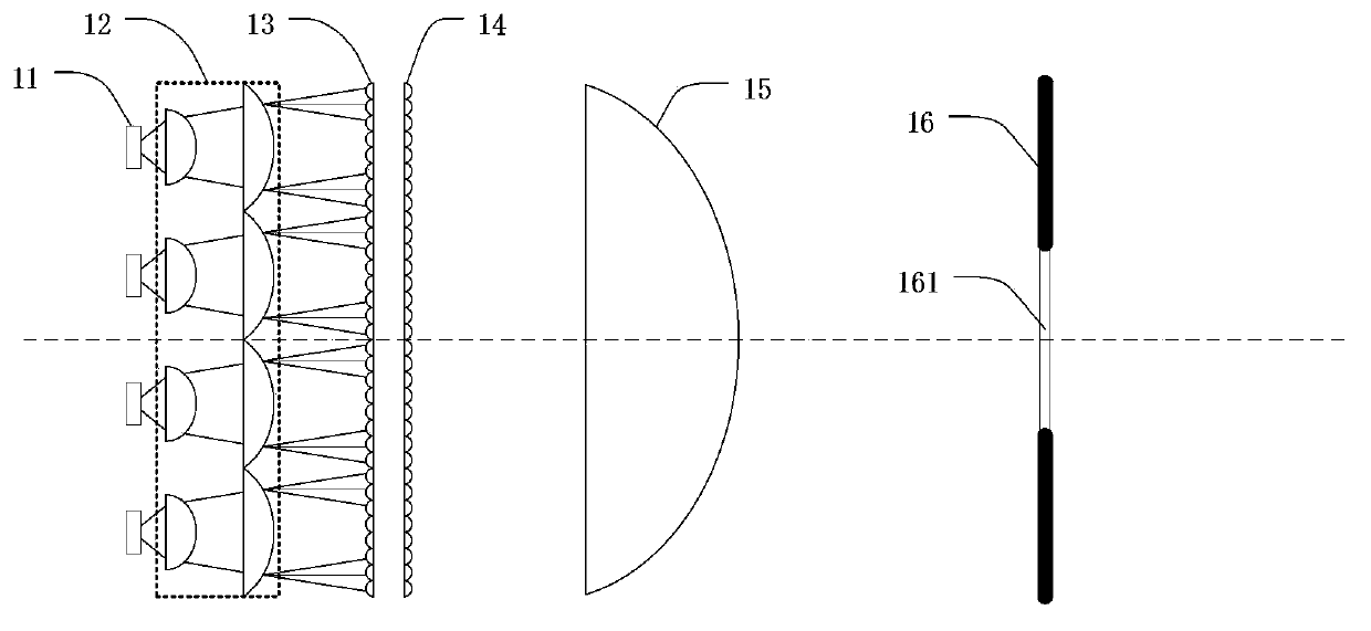
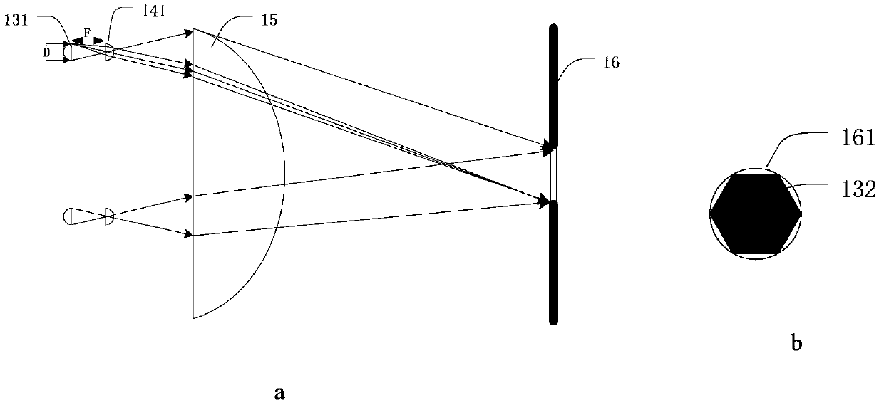
[0034] The overall structure of the light source system of this embodiment is as follows Figure 4 shown. The light source system includes an LED chip array, the LED chip array includes at least two LED chips 41, and the light emitting surface of each LED chip 41 is square. The light source system also includes a collimating lens array 42 positioned behind the LED chip array. The collimating lens array 42 includes at least two collimating lenses, and each collimating lens corresponds to at least one LED chip, and is used to correct the light beam emitted by the LED chip array. Collimating; in this embodiment, a collimating lens is realized by placing two lenses front and back to form a lens group. The light source system also includes a first fly-eye lens 43 positioned behind the collimating lens array 42, the first fly-eye lens 43 includes a regular hexagonal microlens array closely arranged; it also includes a second fly-eye lens 44 positioned at the rear focal plane of the...

Embodiment 2

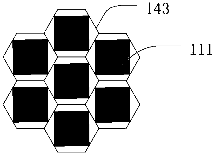
[0043] In the first embodiment, the image of the LED chip cannot be filled in the long side direction of the rectangular microlens, and the etendue is still wasted. In this embodiment, the divergence angle of the LED along the two mutually perpendicular sides of the LED chip after passing through the collimating lens is a predetermined value. According to the formula (1), as long as the LED is controlled to pass through the collimating lens The divergence angle on two mutually perpendicular edge directions is predetermined value, just can control the aspect ratio of the image that LED chip forms on the rectangular microlens of second fly-eye lens; Make this aspect ratio equal to the aspect ratio of rectangular microlens In this way, the image of the LED chip can completely fill the rectangular microlens, and the brightness is the highest at this time.

[0044] For example, the aspect ratio of the rectangular microlens 143 is at most At this time, the corresponding rectangula...


PUM


Abstract

The invention provides an LED light source system and an LED lighting device. The LED light source system comprises an LED chip array, a collimating lens array, a first fly's-eye lens and a second fly's-eye lens, wherein the first fly's-eye lens comprises orthohexagonal microlens arrays which are closely arranged; the second fly's-eye lens comprises rectangular microlens arrays; each rectangular microlens on the second fly's-eye lens and each orthohexagonal microlens on the first fly's-eye lens are in one-to-one correspondence, the center of the rectangular microlens is coincided with the center of the orthohexagonal microlens, and the length of the short edge of the rectangular microlens is equal to 1.5 times of side length of the orthohexagonal microlens on the first fly's-eye lens; two or more edges of the image of each LED chip, which is formed on each rectangular microlens of the second fly's-eye lens after passing through each collimating lens and each orthohexagonal microlens of the first fly's-eye lens, are coincided with the edges of the corresponding rectangular microlens. According to the invention, the image of each LED chip can be well matched with a rectangular clear aperture of the second fly's-eye lens, so that the optical extending amount of the system is reduced, and the brightness is improved.

Description

technical field [0001] The invention relates to the field of light sources such as projection and lighting, and in particular to an LED light source system and an LED lighting device using the LED light source system. Background technique [0002] Traditional high-power stage lighting equipment generally uses metal halide discharge bulbs as light sources. Since the metal halide discharge bulb is a white light source, when it is necessary to generate colored light, it is necessary to install a filter in front of the metal halide discharge bulb to achieve light output of different colors. The disadvantage of this light source is that the service life of the metal halide discharge bulb is low, ranging from only a few hundred hours to thousands of hours; Rich. [0003] High-power light-emitting diodes (LEDs) have gradually become the preferred device for development and application in the field of lighting due to their safety, pollution-free, and long service life, and their s...

Claims


Application Information

Patent Timeline
Patent Type & Authority Applications(China)
IPC IPC(8): F21S2/00F21V5/04F21Y101/02F21K9/69F21Y115/10
Inventor 胡飞
Owner YLX INC
Why Eureka
Try Eureka