
Coaxial coil electromagnetism propulsion system

An electromagnetic propulsion and coaxial coil technology, which is applied to electromagnetic launchers, offensive equipment, weapons without explosives, etc. Precisely control the launch, limit the practicability of the coil gun, etc., to achieve the effect of uniform distribution of induced current, low temperature rise at the tail, and reduced difficulty and complexity

Inactive Publication Date: 2014-08-06
SOUTHWEST JIAOTONG UNIV
View PDF5 Cites 6 Cited by
  • Summary
  • Abstract
  • Description
  • Claims
  • Application Information

AI Technical Summary

Problems solved by technology

[0003] Electromagnetic propulsion technology is a new propulsion method that has emerged in recent decades and has broad application prospects. However, due to some theoretical defects and limitations of some technical problems, this technology is still in the experimental research stage
The electromagnetic railgun is a relatively mature propulsion technology at present. It uses a large current to flow through two parallel guide rails to generate a strong magnetic field to push the armature in contact with the two guide rails. The guide rail and the armature have to bear a huge heat flow impact during the launch process, which is easy to cause serious ablation and surface peeling, and the outlet of the guide rail is prone to arc phenomenon, which seriously affects the service life of the electromagnetic railgun, the exit speed of the projectile and the launch efficiency. improve
Coaxial coil guns and reconnection guns are collectively referred to as coil guns, which have the advantages of large propulsion mass, non-contact ablation, and high emission efficiency. However, due to the limitations of pulse power supply technology, synchronous control technology and switching devices, it is difficult to pass the armature Multiple stages of precisely controlled firing to very high velocities, limiting the usefulness of coilguns

Method used

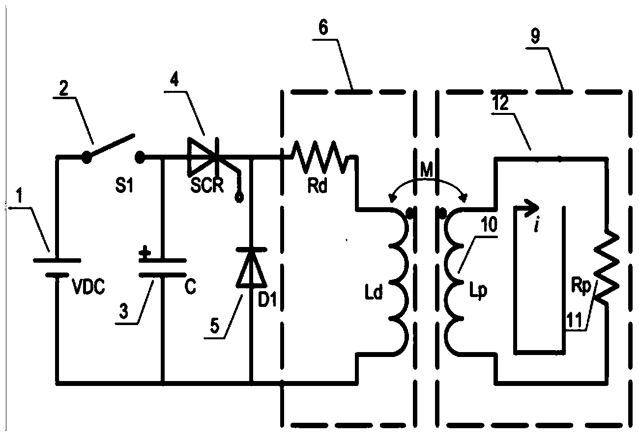

Image

  • Coaxial coil electromagnetism propulsion system
  • Coaxial coil electromagnetism propulsion system
  • Coaxial coil electromagnetism propulsion system

Examples


Embodiment

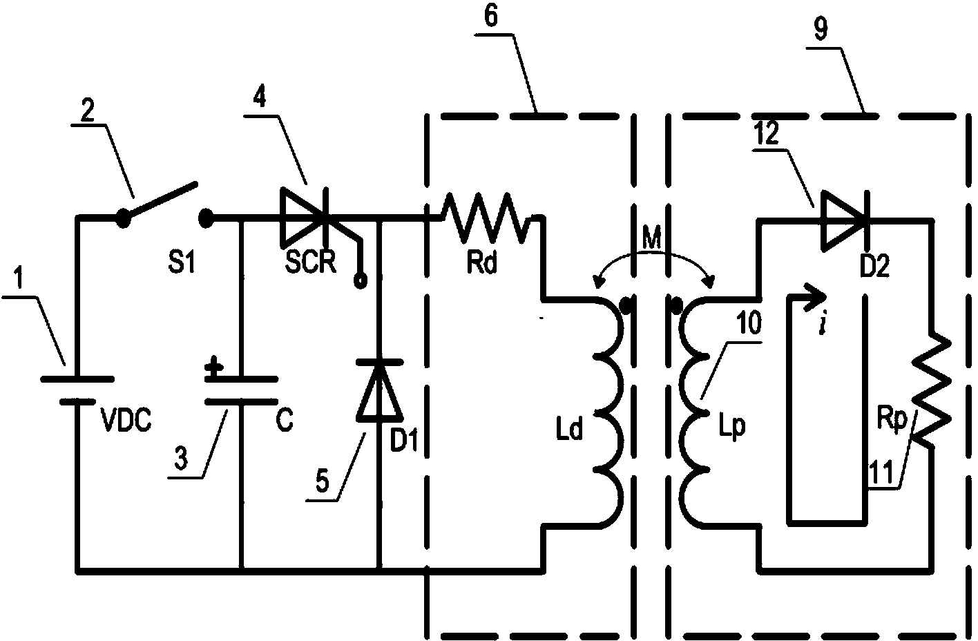
[0018] Such as figure 2 As shown, the relevant parameters of the circuit are as follows:

[0019] High-voltage DC charging power supply: 10kV;

[0020] Pulse capacitor: C=100uF, Uc=6kV;

[0021] Drive coil: internal resistance Rd=0.2Ω, self-inductance Ld=0.296mH;

[0022] Projectile armature: internal resistance Rp=30mΩ, self-inductance Lp=4.1nH;

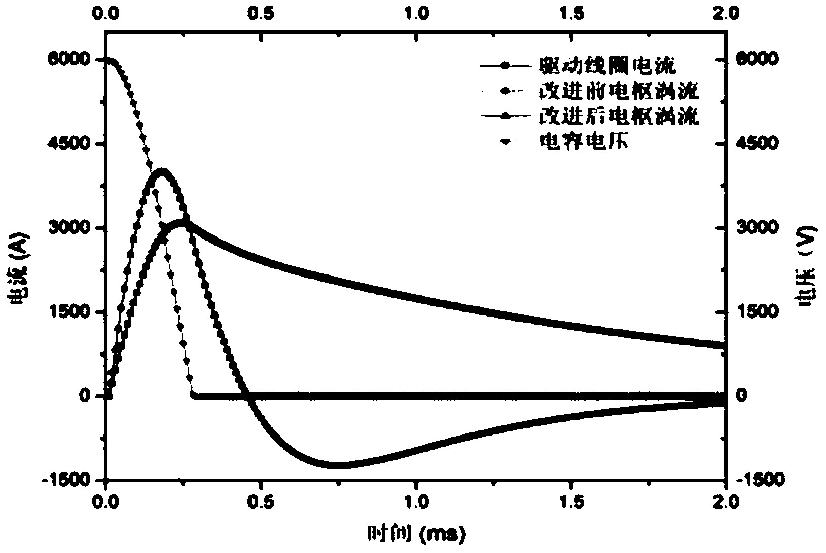
[0023] Such as image 3 As shown, charge the pulse capacitor to the preset voltage of 6kV with a high-voltage DC charging power supply, turn off the switch S1, and the energy storage of the pulse capacitor is completed; within 0~0.28ms, the pulse capacitor discharges the driving coil, and the voltage of the pulse capacitor drops to 0. The current flowing through the drive coil reaches the maximum, the eddy current induced on the projectile armature reaches the maximum, and the controllable switch is automatically turned off; within 0.28~0.45ms, the residual current of the drive coil forms a freewheeling circuit through the diod...


PUM


Abstract

The invention discloses a coaxial coil electromagnetism propulsion system which comprises a driving coil, a projectile armature, a power supply device, a controllable switch, a projectile armature position detecting sensor and a synchronization accuracy control chip. A diode D2 is connected in series to a winding type coil 10 of the projectile armature. Negative force influence caused by armature capturing effect can be completely removed through the armature. For both of a solid armature and a coil type armature, vortexes sensed on the armatures during an electromagnetism propulsion process can flow in double directions, and the armatures can move in acceleration mode under electromagnetism repelling force and move in a deceleration mode under electromagnetism attracting force. Deceleration influence caused by the armature capturing effect is avoided. According to the propulsion feature, the coil type armature is improved, the diode is connected in series to the coil, vortex reverse flow is inhibited, so that only forward-direction acceleration force is exerted on the armature, backward-direction deceleration force is removed, and propulsion performance is improved.

Description

technical field [0001] The invention belongs to the technical field of electromagnetic propulsion, and in particular relates to a device based on coaxial coil electromagnetic propulsion. Background technique [0002] Electromagnetic propulsion technology refers to a device that uses electromagnetic force to propel objects to a certain speed. It was mainly used in military affairs at first, and it is also called electromagnetic gun. Electromagnetic propulsion devices can be divided into three types by type: orbital type, reconnection type and coaxial coil type. [0003] Electromagnetic propulsion technology is a new propulsion method that has emerged in recent decades and has broad application prospects. However, due to some theoretical defects and limitations of some technical problems, this technology is still in the experimental research stage. The electromagnetic railgun is a relatively mature propulsion technology at present. It uses a large current to flow through two ...

Claims


Application Information

Patent Timeline
IPC IPC(8): F41B6/00
Inventor 王豫刘汉军严仲明罗文博张培星
Owner SOUTHWEST JIAOTONG UNIV
Learn More