Mechanical zero adjusting device of steering engine

A technology of mechanical zero position and adjustment devices, which is applied in the direction of adopting mechanical devices, mechanical measuring devices, measuring devices, etc., can solve the problems of low work efficiency, no measuring tools, no measuring reference, etc., and achieve simple structure, simple measurement operation, Intuitive effect of measurement results

Inactive Publication Date: 2014-08-06
HARBIN JIANCHENG GRP
View PDF6 Cites 9 Cited by
  • Summary
  • Abstract
  • Description
  • Claims
  • Application Information

AI Technical Summary

Problems solved by technology

[0003] The purpose of the present invention is to solve the problems that the existing steering gear mechanical zero adjustment relies on angle measurement to adjust the zero position. This adjustment method has the problems of no measurement reference, no measurement tools, low measurement accuracy, complicated operation, and low work efficiency. , and provide a steering gear mechanical zero adjustment device

Method used


Image

  • Mechanical zero adjusting device of steering engine
  • Mechanical zero adjusting device of steering engine
  • Mechanical zero adjusting device of steering engine

Examples


specific Embodiment approach 1

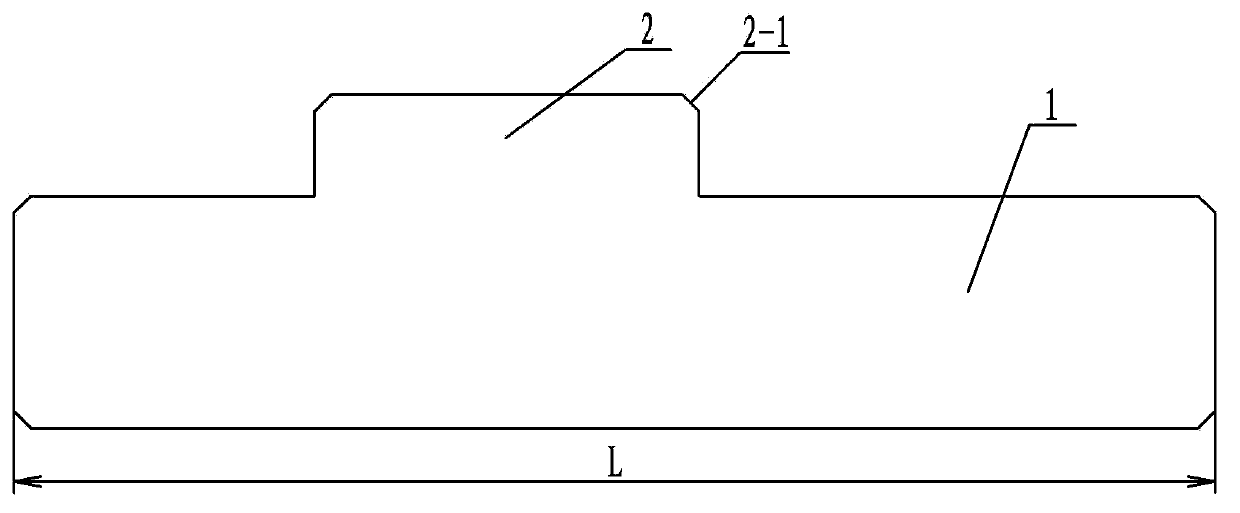
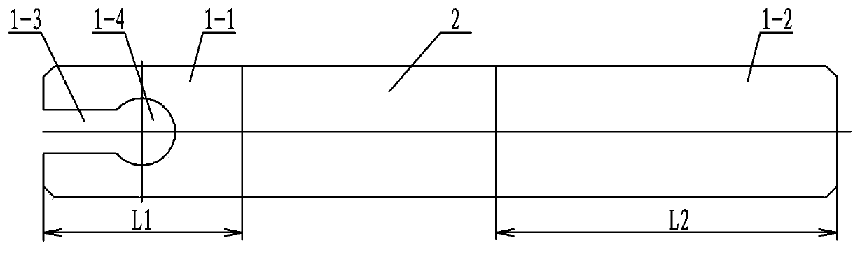
[0007] Specific implementation mode one: combine figure 1 and figure 2 Describe this embodiment, this embodiment includes detection block 1 and positioning block 2, the cross-section of detection block 1 and positioning block 2 is rectangular, positioning block 2 and detection block 1 are set up and down and made into one, positioning block 2 The part between one end of the detection block 1 is the detection end 1-1, the part between the positioning block 2 and the other end of the detection block 1 is the non-detection end 1-2, and the outer end surface of the detection end 1-1 is edge detection A long slot 1-3 is provided in the length direction of the end 1-1, and a pin hole 1-4 communicating with the long slot 1-3 is provided in the detection end 1-1 along the thickness direction. The length L of the detection block 1 is the same as the diameter of the output shaft 4 on the steering gear 3 . The width of long slot 1-3 is slightly larger than the diameter of positioning ...

specific Embodiment approach 2

[0008] Specific implementation mode two: combination figure 1 Referring to this embodiment, chamfers 2-1 are provided at the intersections between the upper end surface of the positioning block 2 and the four side walls in this embodiment. Other components and connections are the same as those in the first embodiment.

specific Embodiment approach 3

[0009] Specific implementation mode three: combination figure 2 The present embodiment will be described. In this embodiment, the length L1 of the detection end 1-1 is smaller than the length L2 of the non-detection end 1-2. Other compositions and connections are the same as those in Embodiment 1 or 2.

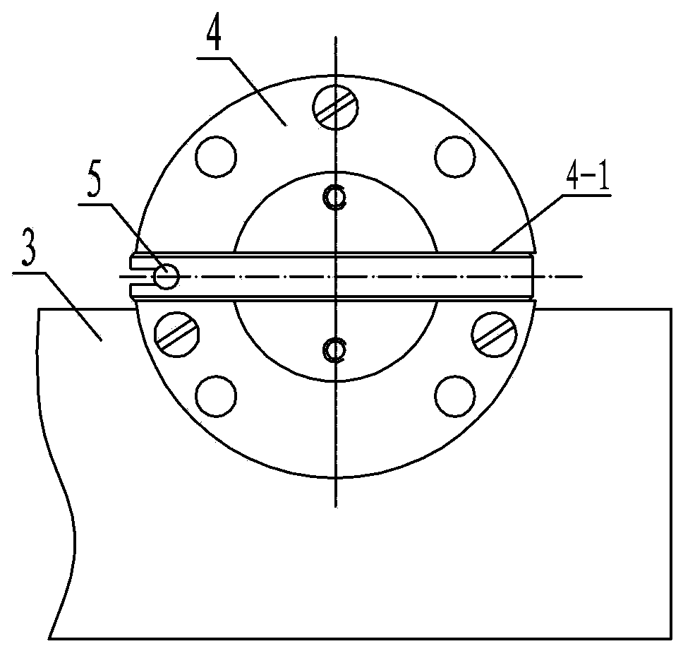
[0010] Using method of the present invention: see image 3 and Figure 4 , first put the detection block 1 into the rectangular groove 4-1 on the output shaft 4 of the steering gear, and rotate the output shaft 4 until the positioning pin 5 on the steering gear 3 can pass through the pin hole 1-4 on the detection block 1 smoothly , it is determined that the mechanical zero position of the steering gear is qualified.


PUM


Abstract

The invention relates to a mechanical zero detecting tool of a steering engine, in particular to a mechanical zero adjusting device of the steering engine. The mechanical zero adjusting device aims to solve the problem that existing mechanical zero adjustment of the steering engine depends on angle measurement, which has no measuring basis and tools, is low in measuring accuracy, complicated in operation and low in operation efficiency. The mechanical zero adjusting device comprises a detecting block and a positioning block, both the detecting block and the positioning block are provided with rectangular cross sections and are arranged up and down and integrated, the portion between the positioning block and one end of the detecting block is a detecting end, and the portion between the positioning block and the other end of the detecting block is a non-detecting end. The outer side end face of the detecting end is provided with an elongated groove along the length direction of the detecting end, and the detecting end is provided with a pin hole communicated with the elongated groove along the thickness direction. The mechanical zero detecting tool is used for mechanical zero detection of the steering engine.

Description

technical field [0001] The invention relates to a tool for detecting the mechanical zero position of a steering gear, in particular to a device for adjusting the mechanical zero position of a steering gear. Background technique [0002] The mechanical zero position of the steering gear requires precise adjustment. The existing mechanical zero position adjustment of the steering gear relies on angle measurement to adjust the zero position. This adjustment method has no measurement reference, no convenient measurement tools, and low measurement accuracy. , can only observe the measurement results with the naked eye, the operation is complicated, the precision is poor, the accuracy is low, and the work efficiency is low. Contents of the invention [0003] The purpose of the present invention is to solve the problems that the existing steering gear mechanical zero adjustment relies on angle measurement to adjust the zero position. This adjustment method has the problems of no ...

Claims


Application Information

Patent Timeline
Patent Type & Authority Applications(China)
IPC IPC(8): G01B5/00
Inventor 闫霞程国锋孙立伟杨春秋石建国李源李忠华刘林炎周大明
Owner HARBIN JIANCHENG GRP
Why Eureka
Try Eureka