

Circuit layout structure of solar cell array
A solar cell array and solar cell technology, applied in circuits, photovoltaic power generation, electrical components, etc., can solve the problems of increasing the length and weight of cables, and achieve the effect of reducing the length and weight
- Summary
- Abstract
- Description
- Claims
- Application Information
AI Technical Summary
Problems solved by technology
Method used
Image

Examples
Embodiment 1
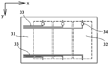
[0040] Embodiment 1: as Figure 10 As shown, two upper and lower rows of solar cell strings are arranged on the front of the substrate 31, and four cable bundles are arranged on the back of the substrate, and the cable bundles are composed of multiple wires. The upper row of solar battery strings 32 corresponds to the cable bundles 335 and 336. One end of the cable bundle 335 is connected in series with the isolation diode 34 and passes through the small hole 36 to connect to the output end of the solar battery string. The other end of the cable bundle 335 is connected to the solar battery array drive mechanism. To connect, one end of the cable bundle 336 is connected to the output end of the solar battery string through the small hole, and the other end of the cable bundle 336 is connected to the solar battery array driving mechanism. For the next row of solar battery strings, use the same method to realize the circuit connection.
Embodiment 2
[0041] Embodiment 2: as Figure 11 As shown, solar battery strings 32 are arranged on the front side of the substrate 31, and every two adjacent solar battery strings are connected in series to form a "U"-shaped battery string through a jumper connecting piece 37, and the positive and negative output terminals of the "U"-shaped battery string are all located on the upper end of the substrate 31 . A bundle of cables 33 is arranged on the back of the substrate. The cable bundle is composed of flat wire cores. One end of the flat wire cores is connected to the solar cell string, and the other end is connected to the solar cell array drive mechanism through an inter-board cable 35 . Two flat cores form a group, one of which bypasses the edge of the substrate and is directly connected to the output end of the "U"-shaped battery string, and the other is connected in series with the isolation diode 34 and then bypasses the edge of the substrate and the output end of the "U"-shaped ba...
Embodiment 3
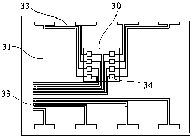
[0042] Embodiment 3: as Figure 12As shown, a solar cell string 32 and an isolation diode 34 are arranged on the front surface of the substrate 31 , and the isolation diode 34 is connected in series at one end of the solar cell string 32 . Two cable bundles 335 and 336 are arranged on the back side of the substrate, and the cable bundles are made of flat wire cores. One end of the cable bundle 335 bypasses the edge of the substrate 31 and is connected to the isolation diode 34, and the other end is directly connected to the solar cell array drive mechanism; one end of the cable bundle 336 is connected to the output end of the solar cell string by bypassing the edge of the substrate 31, and the other end is directly connected to the solar cell array drive mechanism. Connect with the solar array drive mechanism.
[0043] Compared with the prior art, the circuit layout structure of the present invention adopts the scattered arrangement of isolation diodes, and the main part of t...
PUM
| Property | Measurement | Unit |
|---|---|---|
| Thickness | aaaaa | aaaaa |
Abstract
Description
Claims
Application Information