Signal generation circuit

A technology of signal generation circuit and conversion circuit, which is applied in the direction of electric pulse generator circuit, pulse generation, electrical components, etc., can solve the problems of frequency coverage that cannot meet the requirements, technical index requirements, output signal amplitude attenuation, etc., to achieve The output signal is stable and reliable, the circuit cost is low, and the effect of adjustable frequency

Inactive Publication Date: 2014-08-06
SUZHOU INST OF TRADE & COMMERCE
View PDF2 Cites 9 Cited by
  • Summary
  • Abstract
  • Description
  • Claims
  • Application Information

AI Technical Summary

Problems solved by technology

[0003] In the existing waveform generation circuit, the main technical problems are: 1. The waveform distortion is high and cannot meet the technical

Method used


Image

  • Signal generation circuit
  • Signal generation circuit
  • Signal generation circuit

Examples


Embodiment Construction

[0022] The technical solutions in the embodiments of the present invention will be clearly and completely described and discussed below in conjunction with the accompanying drawings of the present invention. Obviously, what is described here is only a part of the examples of the present invention, not all examples. Based on the present invention All other embodiments obtained by persons of ordinary skill in the art without creative efforts fall within the protection scope of the present invention.

[0023] In order to facilitate the understanding of the embodiments of the present invention, specific embodiments will be taken as examples for further explanation below in conjunction with the accompanying drawings, and each embodiment does not constitute a limitation to the embodiments of the present invention.

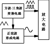
[0024] A waveform generating circuit provided by the present invention includes: an oscillation circuit, a sine wave forming circuit and an output circuit.

[0025] The ...


PUM


Abstract

The invention discloses a signal generation circuit. An operational amplifier and a discrete device are combined to form a square wave-triangular wave generation circuit, and triangular waves are obtained by square waves output by a hysteresis comparator through a comparator. A conversion circuit from the triangular waves to sine waves is mainly completed through a diode and a resistance voltage division circuit. According to the design principle of the conversion circuit, nonlinearity of a transmission characteristic curve of the diode is utilized. Compared with the prior art, the waveform distortion meets the index requirement, the frequency coverage range is large, the frequency is adjustable, output signals are stable and reliable, and the cost of the circuit is low.

Description

technical field [0001] The invention relates to the technical field of basic electronic circuits, in particular to a signal generating circuit. Background technique [0002] The frame diagrams of common waveform generation circuit designs are all in accordance with figure 1 As shown, the waveform generation circuit is used to generate three kinds of signals such as square wave, triangle wave and sine wave. There are three commonly used methods: the first one is to generate square wave, and then transform to get triangle wave and sine wave; the second one is to first Generate a sine wave and then get a square wave and a triangle wave; the third is to generate a triangle wave first and then convert it into a square wave and a sine wave. [0003] In the existing waveform generation circuit, the main technical problems are: 1. The waveform distortion is high and cannot meet the technical index requirements; 2. The frequency coverage cannot meet the requirements; 3. The output...

Claims


Application Information

Patent Timeline
IPC IPC(8): H03K3/02H03K3/80H03K4/06
Inventor 戴锐青汤伟芳乔磊
Owner SUZHOU INST OF TRADE & COMMERCE
Why Eureka
Try Eureka