Automatic robot welding work station

An automatic welding and robotic welding technology, applied in welding equipment, welding equipment, auxiliary welding equipment, etc., can solve the problem of low welding efficiency of welding workbench, achieve the effect of improving welding efficiency, improving utilization rate, and avoiding idle time

Inactive Publication Date: 2014-08-13
肖宁
View PDF8 Cites 10 Cited by
  • Summary
  • Abstract
  • Description
  • Claims
  • Application Information

AI Technical Summary

Problems solved by technology

[0004] The purpose of the present invention is to provide a robot automatic welding workstation to solve the technical problem of low welding efficiency of the existing welding workbench

Method used


Image

  • Automatic robot welding work station
  • Automatic robot welding work station
  • Automatic robot welding work station

Examples


Embodiment Construction

[0022] In order to make the object, technical solution and advantages of the present invention clearer, the implementation manner of the present invention will be further described in detail below in conjunction with the accompanying drawings.

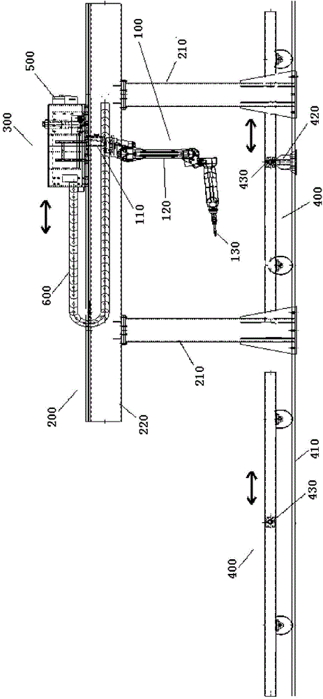
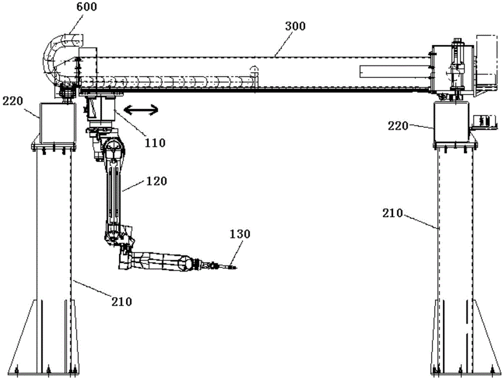
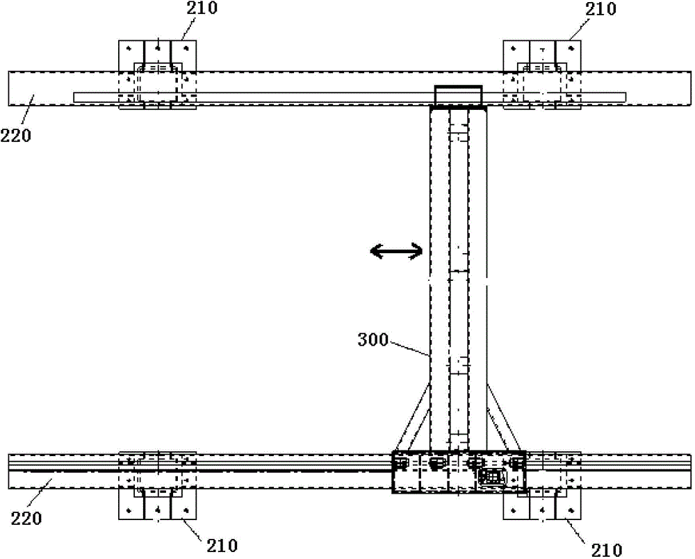
[0023] combine Figure 1-Figure 3 A specific embodiment of the present invention is shown, in order to make the accompanying drawings simple and clear, figure 2 and image 3 The rolling table is not shown. As shown in the figure, the present invention provides a robot automatic welding workstation, which includes a robot welding unit 100 , a gantry structure unit 200 , a walking beam 300 and two rolling workbenches 400 . In the workstation of the present invention, on the one hand, through the cooperative action of the gantry structure unit 200 and the walking beam 300, the robot welding unit 100 can move linearly along the x-axis and y-axis in the horizontal plane, and the linear movement of the x-axis and y-axis refers to Move al...


PUM


Abstract

The invention discloses an automatic robot welding work station. The work station comprises a robot welding unit, a gantry structural unit, a walking beam and two rolling work stations, wherein the walking beam is arranged on the gantry structural unit and can move reciprocally in a horizontal plane along the direction which is perpendicular to the axial direction of the walking beam; the robot welding unit is mounted on the walking beam in an inversely suspended way and can move reciprocally along the axial direction of the walking beam; the rolling work stations are used for clamping a piece to be welded, and can move reciprocally along the direction which is perpendicular to the axial direction of the walking beam, so that the two rolling work stations are positioned below the walking beam alternately; the robot welding unit welds continuously. The automatic robot welding work station provided by the invention is used for solving the technical problem that the conventional robot work station is low in welding efficiency.

Description

technical field [0001] The invention belongs to the field of welding equipment, and in particular relates to a robot automatic welding workstation. Background technique [0002] With the widespread application of robots in industry, more and more factories have begun to use robots to weld large structural parts such as electrical roofs. On the one hand, due to the large size and complex structure of the workpiece itself, the traditional robot welding workbench mostly welds the electrical roof from one side only through the action of the robot itself, and it is difficult to weld the electrical roof, etc. only through the action of the robot itself. Carry out all-round welding; on the other hand, due to the large size and complex structure of the workpiece itself, the manual hoisting, assembly, and welding processes are very cumbersome, and the above processes are difficult to cooperate with the high-efficiency operation of robot welding. Therefore, the utilization rate of th...

Claims


Application Information

Patent Timeline
Patent Type & Authority Applications(China)
IPC IPC(8): B23K37/00B23K31/02
CPCB23K37/0461B23K31/02B23K37/02
Inventor 邵立早马明孙承政薛海涛
Owner 肖宁
Why Eureka
Try Eureka