
Air noise reduction structure of the front pillar

A front pillar, pillar technology, applied in the superstructure, superstructure sub-assemblies, windows and other directions to achieve the effect of reducing wind friction sound

Inactive Publication Date: 2016-03-16
SUZUKI MOTOR CORP
View PDF6 Cites 0 Cited by
  • Summary
  • Abstract
  • Description
  • Claims
  • Application Information

AI Technical Summary

Problems solved by technology

In such a vehicle, since the air detours less to the side of the vehicle body, the air noise as described above is small, but the air itself can be suppressed by increasing the step from the windshield to the front pillar. Detour to the side of the body, but this countermeasure cannot be taken in vehicles with a large windshield rise angle

Method used


Image

  • Air noise reduction structure of the front pillar
  • Air noise reduction structure of the front pillar
  • Air noise reduction structure of the front pillar

Examples


Embodiment Construction

[0027] Hereinafter, embodiments of the present invention will be described in detail with reference to the drawings.

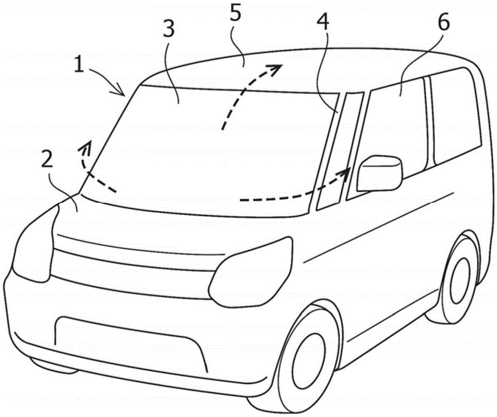
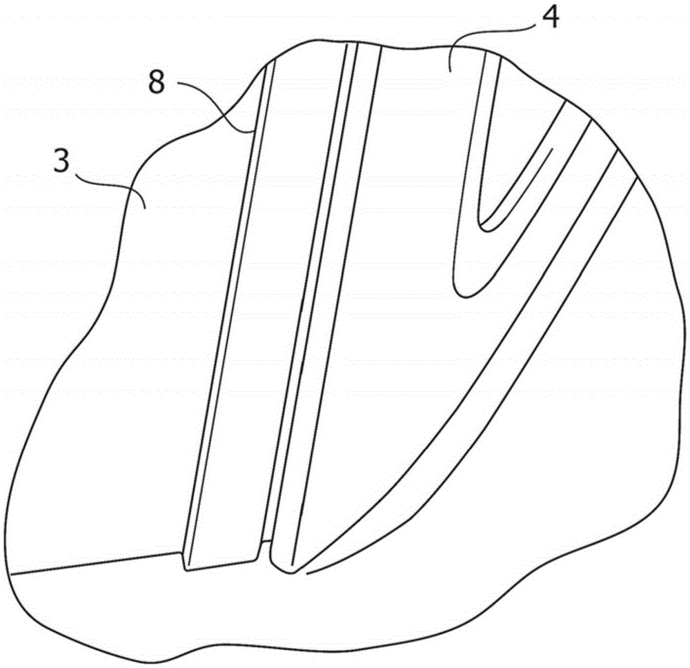
[0028] figure 1 It shows a typical vehicle 1 implementing the air noise reduction structure of the present invention. The vehicle 1 is a small car with a hood 2 (hood) at the front, and includes a windshield with a large rising angle in order to secure a space for the passenger compartment. Glass 3 and front pillar 4.

[0029] In such a vehicle 1, the airflow received from the front by the windshield 3 when the vehicle is running is guided by the inclination of the windshield 3 to the roof 5 side, or guided by the curvature of the windshield 3 to the vehicle body. As shown in the example of the figure, when the front pillar 4 and the windshield 3 are upright, the air flow tends to detour from the front pillar 4 to the vehicle body side 6 significantly.

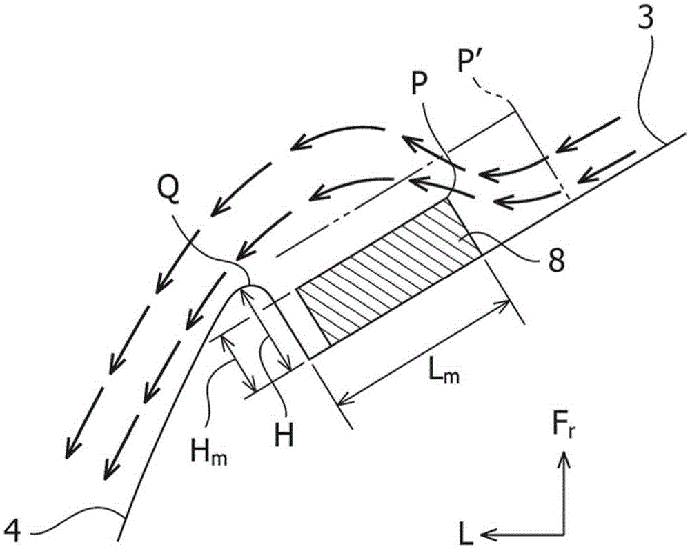
[0030] At this time, near the front pillar 4, such as Figure 4 As shown, the air flow flowing along th...


PUM


Abstract

The air noise reducing front pillar structure has a pillar fitting, which is molded with a quadratic cross sectional design orthogonal to a longitudinal direction. The width from the vertical wall surfaces to the front end edge lies in a range of 1.5 to 3 times the height of the pillar ribs sections based on the windshield surface. A ratio of the height of the front end edge to the width up to the front end edge lies in a range of 0.2 to 0.4.

Description

technical field [0001] The present invention relates to an air noise reduction structure of a front pillar portion of a vehicle. Background technique [0002] In small vehicles, etc., where rideability and compactness are emphasized, the rising angles of the front pillars and the windshield are set to be large. When the vehicle is running, the windshield received air flow from the front to the roof side and the sides of the body, but when the front pillars and the windshield are upright, the air flow tends to detour from the front pillars to the side of the body. significantly. [0003] At this time, in the front pillar portion, the airflow flowing in the vehicle width direction separates from the vehicle body surface while rapidly deflecting rearward over the step from the windshield, and vortices are generated on the side of the vehicle body. [0004] When the eddy current collides with the main flow flowing rearward of the side portion of the vehicle body, air noise is ...

Claims


Application Information

Patent Timeline
Patent Type & Authority Patents(China)
IPC IPC(8): B62D25/04B60J1/20
CPCB62D35/008B62D25/04B62D35/00
Inventor 三浦淳史松野孝浩新美大辅中村笃史
Owner SUZUKI MOTOR CORP
Learn More