Upper machine head of independently-driven rotary type automatic sewing device

An independent drive and rotary technology, applied in sewing machine components, needle holders for sewing machines, control devices for sewing machines, etc., can solve the problems of the upper machine head not being able to lift, the sewing effect is poor, and the product design requirements cannot be met. Simple and convenient maintenance, expanded scope of application, and high degree of integration

Active Publication Date: 2014-08-13
浙江锦上智控科技有限公司
View PDF9 Cites 23 Cited by
  • Summary
  • Abstract
  • Description
  • Claims
  • Application Information

AI Technical Summary

Problems solved by technology

However, the upper and lower machine heads cannot rotate at the same time. Generally, only the lower machine head rotates and the upper machine head does not rotate, which cannot simulate the manual sewing process. Moreover, when reverse sewing, the sewing effect is poor and cannot meet the product design requirements.
[0006] The upper head of the traditional automatic sewing equipment cannot be raised and lowered, and cannot adapt to the thickness change of the fabric to be sewn, which limits the scope of use of the sewing equipment
The existing automatic sewing equipment does not have a presser foot, which cannot guarantee the stability of the fabric and stitches during sewing, and also reduces the scope of use of sewing equipment

Method used


Image

  • Upper machine head of independently-driven rotary type automatic sewing device
  • Upper machine head of independently-driven rotary type automatic sewing device
  • Upper machine head of independently-driven rotary type automatic sewing device

Examples


Embodiment Construction

[0030] In order to make the technical problems, technical solutions and beneficial effects to be solved by the present invention clearer, the present invention will be further described in detail below in conjunction with the accompanying drawings and embodiments. It should be understood that the specific embodiments described here are only used to explain the present invention, not to limit the present invention.

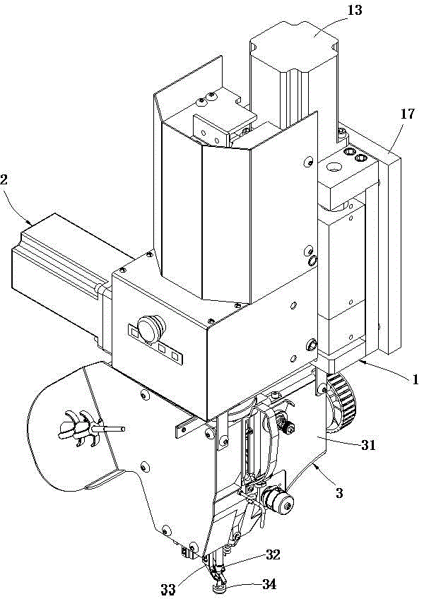
[0031] Please refer to figure 1 As shown, the preferred embodiment of the upper machine head of the independent drive rotary automatic sewing equipment of the present invention is installed directly above the lower machine head, and the upper machine head includes the machine head lifting assembly 1, the machine head rotating assembly 2 and the machine head assembly 3. The head rotating assembly 2 is fixed on the head lifting assembly 1 , and the head assembly 3 is fixed on the bottom of the head rotating assembly 2 . The machine head rotating assembly 2 can driv...


PUM


Abstract

The invention relates to an upper machine head of an independently-driven rotary type automatic sewing device. The upper machine head comprises a machine head lifting assembly, a machine head rotating assembly and a machine head assembly, wherein the machine head rotating assembly is fixedly arranged on the machine head lifting assembly; the machine head assembly is fixedly arranged at the lower part of the machine head rotating assembly; the machine head rotating assembly comprises a conductive slip ring, a slip ring fixing seat, a machine head installation plate, a machine head rotating motor, a gearbox and a rotating shaft, the upper end of the rotating shaft is connected with the conductive slip ring for driving the conductive slip ring to rotate, and the rotating shaft can drive the machine head assembly to rotate clockwise or anticlockwise by 360 degrees; the machine head lifting assembly can drive the machine head assembly to move up and down through the machine head rotating assembly. The upper machine head disclosed by the invention can be lifted and can be rotated as well, various machining needs can be met, and the application range is greatly enlarged; the size is small, the integration degree is high, the upper machine head can be matched with a lower machine head for realizing synchronous high-speed rotating, the stability is high, the failure rate is low, and the maintenance is simple and convenient.

Description

[0001] technical field [0002] The invention relates to the technical field of sewing machines, in particular to an upper head of an independently driven rotary automatic sewing device. [0003] Background technique [0004] A traditional automatic sewing mechanism generally includes an upper head and a lower head, and the upper head drives the lower head to move synchronously through a transmission mechanism to realize the sewing action. The existing transmission mechanism is complicated, the failure rate is high, and maintenance is troublesome. Moreover, the upper and lower machine heads cannot rotate, and can only sew straight lines. When the needle path changes direction, manual processing is required, and the production efficiency is low. [0005] In the prior art, although there have been automatic sewing equipment driven independently by the upper and lower heads, the upper and lower heads can be linked simultaneously by a servo system to complete the sewing action....

Claims


Application Information

Patent Timeline
Patent Type & Authority Applications(China)
IPC IPC(8): D05B69/12D05B69/10D05B29/06D05B55/14D05B69/00
Inventor 王建炳
Owner 浙江锦上智控科技有限公司
Why Eureka
Try Eureka