Monitoring equipment mounting frame

A technology for monitoring equipment and mounting racks, which is applied to mechanical equipment, machines/brackets, supporting machines, etc., can solve the problems of monitoring dead ends, difficult to install cameras, and inability to see equipment images, so as to achieve convenient handling and storage, and protect people. The effect of device security

Active Publication Date: 2016-03-02
STATE GRID CORP OF CHINA +1
View PDF6 Cites 0 Cited by
  • Summary
  • Abstract
  • Description
  • Claims
  • Application Information

AI Technical Summary

Problems solved by technology

[0002] In the existing substation video monitoring system, all the cameras are fixed on the wall. Although the current cameras mostly use dome cameras or pan-tilts, and the camera angle can be rotated 360 degrees, there are still many monitoring dead spots.
Especially in the substation switch room, such as the top of the switch cabinet, bus bridge, etc., because it is not easy to install cameras around it, and the equipment image cannot be seen only by the camera installed on the wall of the switch room. Observed device status

Method used


Image

  • Monitoring equipment mounting frame
  • Monitoring equipment mounting frame
  • Monitoring equipment mounting frame

Examples


Embodiment Construction

[0023] The present invention is described in detail below in conjunction with accompanying drawing:

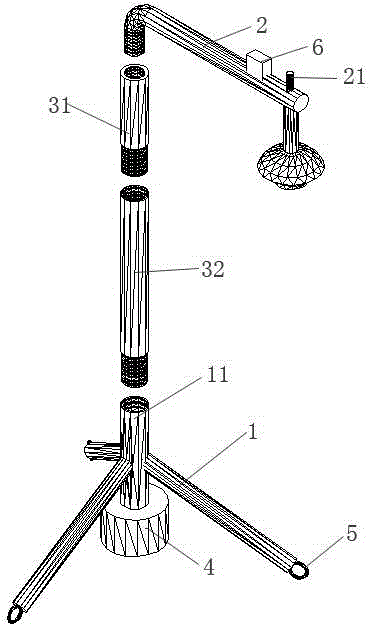
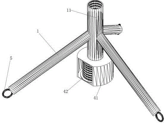
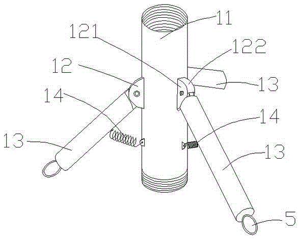
[0024] Such as Figure 1 to Figure 7 As shown (for the convenience of drawing, figure 1 , figure 2 and image 3 The caster 5 on the base of the middle tripod is only a schematic diagram, and the specific structure can be seen Figure 4 ; figure 1 Some structures of the cable storage box in are also omitted, the specific structure can be seen Figure 5 and Figure 6 ;for figure 1 and figure 2 The foot rod in the picture is directly fixed on the metal pipe, and the hinge part is not drawn. For the specific hinge method, see image 3 structure), the specific embodiment of the present invention comprises tripod base 1, equipment installation bar 2 and several struts, figure 1 Only two of the first strut 31 and the second strut 32 are shown in the figure. A camera dome mounting seat is arranged on the lower side of the end of the equipment installation rod 2, and a came...


PUM


Abstract

A monitoring device installation frame comprises a tripod base, a device installation rod and a plurality of supporting rods; the center of the tripod base is vertically provided with a metal pipe; three foot rods of the tripod base are hinged to the metal pipe; a tension spring is arranged between the metal pipe and every foot rod; the lower end of every foot rod is provided with a castor which is provided with a braking device; the supporting rods can be in thread connection with the upper end of the metal pipe; the lower end of the metal pipe is provided with a cable storage box; the front end of the device installation rod is provided with an electric field sensing alarming device. According to the monitoring device installation frame, assembling can be performed according to requirements and dead-angle-free monitoring is achieved; when the monitoring device installation frame is not used, the foot rods on the tripod base can automatically retract and carrying and storage are convenient; the casters which are provided with brake blocks are arranged on the tripod base, so that the monitoring device installation frame can be pulled according to perambulating positions and the castors can be fixed after the monitoring device installation frame arrives at the perambulating positions.

Description

technical field [0001] The invention relates to a monitoring device fixing device, in particular to a conveniently movable monitoring device installation frame for solving dead angles in substation equipment monitoring. Background technique [0002] In the existing substation video monitoring system, all the cameras are fixed on the wall. Although the current cameras are mostly ball cameras or pan-tilts, and the camera angle can be rotated 360 degrees, there are still many monitoring dead spots. Especially in the substation switch room, such as the top of the switch cabinet, bus bridge, etc., because it is not easy to install cameras around it, and the equipment image cannot be seen only by the camera installed on the wall of the switch room. Observed device status. Contents of the invention [0003] In order to overcome the above-mentioned shortcomings in the prior art, the purpose of the present invention is to provide a monitoring equipment installation frame that can ...

Claims


Application Information

Patent Timeline
Patent Type & Authority Patents(China)
IPC IPC(8): F16M11/26
Inventor 俄立波张来苏楠李哲康润泽张清伦
Owner STATE GRID CORP OF CHINA
Why Eureka
Try Eureka