Micro vibration measuring system and measuring method based on long-distance pulse laser speckles

A pulsed laser, measurement system technology, applied in measurement devices, measurement of ultrasonic/sonic/infrasonic waves, instruments, etc., can solve the problems of the reduction of the echo power reaching the photodetector, adverse effects of measurement, etc., and avoid the large-scale echo power. The effect of reducing, ensuring quality, and increasing echo power

Active Publication Date: 2014-08-13
XIAMEN UNIV
View PDF2 Cites 24 Cited by
  • Summary
  • Abstract
  • Description
  • Claims
  • Application Information

AI Technical Summary

Problems solved by technology

However, the addition of a spatial filter or aperture template with a small aperture will inevitably reduce the echo power reaching the photodetector, which will have an adverse effect on the measurement, especially in long-distance measurement or low reflectivity of the target in the case of

Method used


Image

  • Micro vibration measuring system and measuring method based on long-distance pulse laser speckles
  • Micro vibration measuring system and measuring method based on long-distance pulse laser speckles

Examples


Embodiment 1

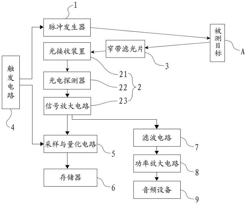
[0027] see figure 1 , a micro-vibration measurement system based on long-distance pulse laser speckle, including pulse laser 1, light detection unit 2, narrow-band filter 3, trigger circuit 4, sampling and quantization circuit 5, memory 6, filter circuit 7, power Amplifying circuit 8 and audio equipment 9, wherein:

[0028] The pulsed laser 1 is used to emit pulsed laser with high peak power and high repetition rate to irradiate the measured target A, and the emission wavelength can be visible light wavelength or infrared wavelength. In this embodiment, the pulsed laser 1 is a Q-switched laser.

[0029] refer to figure 1 As shown, the light detection unit 2 includes a light receiving device 21, a photodetector 22 and a signal amplification circuit 23, wherein:

[0030] The light receiving device 21 is used to receive the speckle generated by the diffuse reflection of the pulsed laser light by the measured target A, and has a certain receiving aperture. In this embodiment, ...

Embodiment 2

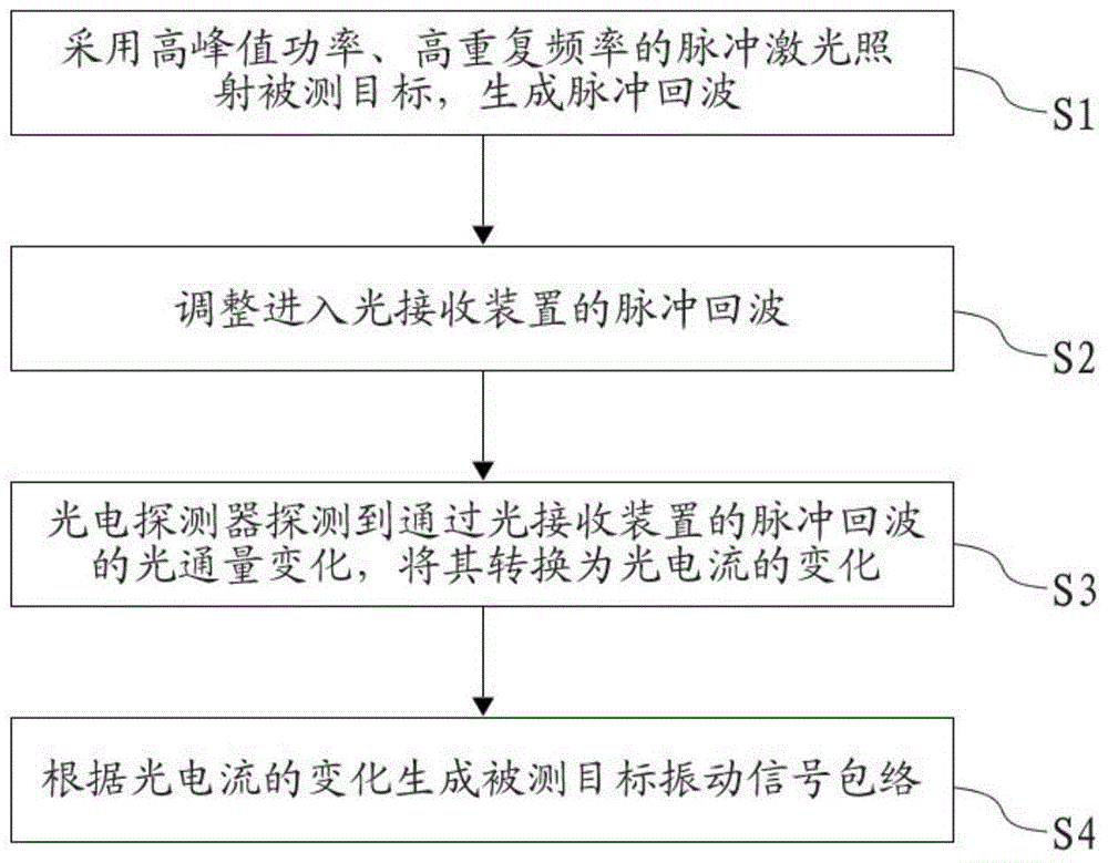
[0039] see figure 1 with figure 2 As shown, a micro-vibration measurement method based on long-distance pulsed laser speckle, including the following steps:

[0040] S1. Pulse laser 1 emits pulsed laser light with high peak power and high repetition frequency to irradiate the target A to be measured and generate pulse echo. The repetition frequency of the pulse laser should be greater than twice the highest vibration frequency of the target A to be measured. The "pulse echo" mentioned here refers to the speckle generated after the pulsed laser is diffusely reflected by the target A under test.

[0041] S2. Adjust the pulse echo entering the light receiving device 21 so that the variation of its luminous flux and the vibration amplitude and frequency of the measured target A are optimally matched. This step is specifically implemented by the following methods:

[0042] By adjusting the spot size of the pulsed laser 1 irradiating the target A to be measured and the receiving...


PUM


Abstract

The invention discloses a micro vibration measuring system based on long-distance pulse laser speckles. The system comprises a pulse laser device and an optical detection unit, wherein the pulse laser device is used for sending pulse laser which is high in peak power and repetition frequency to illuminate a target to be measured; the optical detection unit is used for receiving the speckles, generated by diffuse reflection of the target to be measured, of the pulse laser. The pulse laser light source with high peak power and repetition frequency takes the place of a continuous wave laser light source, so that on the premise that measurement safety is guaranteed, namely average laser emission power is low, echo power fed back by the target to be measured is greatly improved, micro vibration measuring of the long-distance target can be achieved, and the method has very important actual application value in the fields of bridge and building health monitoring, security protection system, detection and antiterrorism, disaster rescue and the like.

Description

technical field [0001] The invention relates to the technical field of laser speckle vibration measurement, in particular to a micro-vibration measurement system and measurement method based on long-distance pulsed laser speckle. Background technique [0002] The non-contact fixed-point measurement of the tiny vibration of long-distance diffuse reflection non-cooperative targets by laser has very important application significance in the fields of bridge and building health detection, security system, detection and anti-terrorism, disaster search and rescue, etc. However, when the measurement distance is long, the laser echo returned from the detection target will be very weak, making it difficult to detect. Although the detection distance can be increased to a certain extent by increasing the laser power, considering the safety and concealment of the measurement, the laser emission power cannot be increased without limit. [0003] Micro-vibration measurement based on laser...

Claims


Application Information

Patent Timeline
Patent Type & Authority Applications(China)
IPC IPC(8): G01H9/00
Inventor 王程黄朝红付宏燕王晓忠
Owner XIAMEN UNIV
Why Eureka
Try Eureka