
Method and device for improving echo signal of chaotic optical time domain reflectometer

A time-domain reflectometer and echo signal technology, which is applied in the direction of electromagnetic transmitters, electromagnetic wave transmission systems, electrical components, etc., can solve the problems of detection signal propagation attenuation, increase the transmission signal, increase measurement costs, etc., to achieve accurate detection, The effect of high detection accuracy and low cost

Active Publication Date: 2022-07-15
深圳市矽赫科技有限公司
View PDF6 Cites 0 Cited by
  • Summary
  • Abstract
  • Description
  • Claims
  • Application Information

AI Technical Summary

Problems solved by technology

[0004] However, with the application of chaotic optical time domain reflectometer, it is found in practice that the detection signal will be attenuated when propagating in the optical fiber, and the measured echo signal is very small. If the echo signal is too small, the measurement result will be seriously disturbed
At present, there are two main ways to improve the echo signal: one is to increase the power of the transmitted signal, too high power requires a high-power laser, and the other is to increase the sensitivity of the photodetector, but both methods will Increased cost of measurement

Method used


Image

  • Method and device for improving echo signal of chaotic optical time domain reflectometer
  • Method and device for improving echo signal of chaotic optical time domain reflectometer
  • Method and device for improving echo signal of chaotic optical time domain reflectometer

Examples


Embodiment Construction

[0032] The technical solutions in the embodiments of the present invention will be clearly and completely described below with reference to the accompanying drawings in the embodiments of the present invention. Obviously, the described embodiments are only a part of the embodiments of the present invention, but not all of the embodiments. Based on the embodiments of the present invention, all other embodiments obtained by those of ordinary skill in the art without creative efforts shall fall within the protection scope of the present invention.

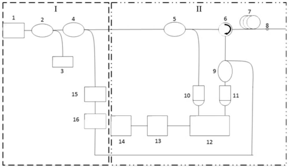
[0033] 1. Please refer to figure 1 As shown, the present invention provides a device for improving the echo signal of a chaotic optical time domain reflectometer. The device includes two parts, I and II, wherein the first part is: figure 1 The chaotic light source emitting part on the left side of the middle, and the part II is figure 1 The optical fiber fault detection component on the right side of the middle; the structure of the ...


PUM


Abstract

The invention belongs to the technical field of optical time domain reflectometers, and discloses a method and a device for improving the echo signal of a chaotic optical time domain reflectometer, wherein the device is used to realize the method, and the method includes the following steps: S1 , Based on a fiber coupler, the light source signal from the feedback laser is divided into two channels, one is connected to the mirror, and the other is directly output to form a chaotic laser source signal; based on another fiber coupler, the chaotic laser source signal is divided into two channels , one output forms a coherent coupled light source signal, and the other output forms a chaotic detection light source signal; the present invention can effectively improve the echo power of the chaotic optical time domain reflectometer based on the coherent coupling enhancement technology, thereby improving the measurement effect of the chaotic optical time domain reflectometer , so that the present invention can realize the detection of the fault point of the optical fiber more accurately, and also has the advantage of low cost.

Description

technical field [0001] The invention belongs to the technical field of optical time domain reflectometers, and in particular relates to a method and a device for improving the echo signal of a chaotic optical time domain reflectometer. Background technique [0002] Optical time domain reflectometer is currently the main measuring instrument for diagnosing fault points of optical fiber links. This equipment uses the pulse flight method measurement technology. It has a simple structure and mature method, but it cannot improve the measurement accuracy and increase the Measure distance. This is because it has irreconcilable contradictions in principle. If you want to increase the farthest distance of the measurement, you must either increase the pulse power or increase the pulse width. Too high pulse optical power will not only increase the measurement cost, but also lead to the loss of the fiber. irreversible damage, and increasing the pulse width will reduce the accuracy of t...

Claims


Application Information

Patent Timeline
Patent Type & Authority Patents(China)
IPC IPC(8): H04B10/071H04B10/079H04B10/50
CPCH04B10/071H04B10/503H04B10/5057H04B10/0791
Inventor 洪鹏达薛欣洪鹏辉洪宝璇林基远
Owner 深圳市矽赫科技有限公司
Learn More