
Optical detection assembly based on all-fiber bias light suppression technology and near-field signal dynamic range suppression technology in laser radar

A technology of laser radar and optical detection, applied in optical components, optics, radio wave measurement systems, etc., can solve the problems of low utilization rate of optical signals, weak echo signals, complex optical paths of receivers, etc., and achieve the integration of high and low altitude The effect of detecting, avoiding near-field signal saturation, and improving operation stability

Inactive Publication Date: 2013-06-12
UNIV OF SCI & TECH OF CHINA
View PDF4 Cites 0 Cited by
  • Summary
  • Abstract
  • Description
  • Claims
  • Application Information

AI Technical Summary

Problems solved by technology

The disadvantages of these two methods are that the optical path of the receiver is complicated, the cost is high, and the utilization rate of the optical signal is low. Especially when the optical signal entering the detector is weakened when detecting the upper atmosphere, the detection accuracy and altitude are reduced.
For middle and high-level laser radar atmospheric detection, the echo signal is weak, which belongs to weak signal or even weak signal detection. Background noise reduces the signal-to-noise ratio, and even causes the saturation of the detector, making the laser radar unable to work. Noise reduces the sensitivity of the detector, and filtering background noise is very important for weak signal detection, which has always been a technical difficulty
At present, in LiDAR, most of the background light suppression is realized through space optics, and the space optical path structure has a large loss and poor stability.

Method used


Image

  • Optical detection assembly based on all-fiber bias light suppression technology and near-field signal dynamic range suppression technology in laser radar
  • Optical detection assembly based on all-fiber bias light suppression technology and near-field signal dynamic range suppression technology in laser radar
  • Optical detection assembly based on all-fiber bias light suppression technology and near-field signal dynamic range suppression technology in laser radar

Examples


Embodiment

[0034] The present invention will be further described below in conjunction with embodiment, but should not limit the protection scope of the present invention with this.

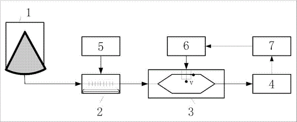
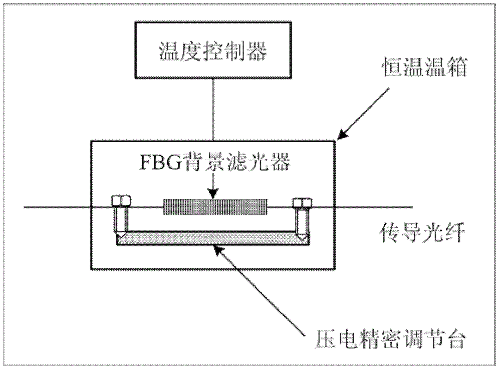
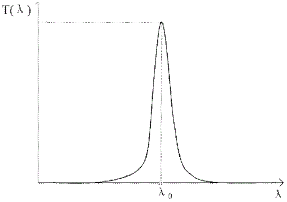
[0035] 1) if figure 1 As shown, the atmospheric molecule scattering signal passes through the receiving telescope 1 to the FBG background filter 2. The FBG background filter 2 is a narrow-band, low-loss transmission filter with a current bandwidth of 0.1nm and a peak transmittance of 99%. The echo signal After FBG background filter 2, the center frequency is υ 0 The optical signal transmittance is 99%, and the optical signals of other frequency bands are filtered out, which effectively suppresses the background light. The FBG background filter 2 is packaged in a constant temperature box. Calculate the temperature stability index according to the temperature influence coefficient. Then the FBG background filter 2 is installed on a precision translation stage, and its stress distribution is controlled by p...


PUM


Abstract

The invention discloses an optical detection assembly based on an all-fiber bias light suppression technology and a near-field signal dynamic range suppression technology in laser radar. The optical detection assembly adopts an FBG (fiber bragg grating) background filter to filter out background noises, and is characterized in that temperature compensation and FBG axial stress control are utilized, so that the peak transmittance position of the FBG background filter is just positioned at the operation wavelength position of the laser radar, the bias light is effectively suppressed, and all-day detection is realized; a light intensity regulator is utilized to regulate the intensity of an optical signal received by the laser radar, and can actively and electrooptically regulate the dynamic range of the signals of the laser radar according to the characteristic of an echoed signal, therefore on the premise of ensuring the maximum signal to noise ratio of a remote signal, near-field signals can be suppressed, the near-field signal saturation of a photodetector can be avoided, the laser emergent power and the echo power of a far-field object are improved, and high-altitude and low-altitude integral detection can be realized; and all-fiber connection is utilized, thus the system operation stability is improved. The optical detection assembly disclosed by the invention has the advantages that the light path cost is greatly lowered, the light path system is simpler, and light path regulation can be carried out conveniently.

Description

technical field [0001] The invention relates to laser radar technology, in particular to an optical detection component for suppression of all-fiber background light and near-field signal dynamic range suppression technology in laser radar. Background technique [0002] Lidar is the product of the combination of traditional radar technology and modern laser technology. With the rapid development of laser technology and the application of advanced signal detection and data acquisition systems, lidar has become an important active remote sensing tool due to its high measurement accuracy, fine time and space resolution, and large detection span. It has shown its unique advantages and development potential in the remote measurement of atmospheric wind field, temperature field, turbulence, atmospheric composition and backscattering coefficient. With the research and application of high-tech equipment, the detection of low-level and even middle-level and upper-level atmospheric p...

Claims


Application Information

Patent Timeline
Patent Type & Authority Patents(China)
IPC IPC(8): G02B27/00G02B23/00G01S7/487
CPCY02A90/10
Inventor 窦贤康韩燕夏海云孙东松薛向辉陈廷娣
Owner UNIV OF SCI & TECH OF CHINA
Learn More