
Mechanical failure debugging device for rotor craft

A technology for rotorcraft and mechanical failure, applied in electrical testing/monitoring and other directions, can solve the problems of not considering the mechanical installation accuracy of the rotorcraft, wiring errors, errors, etc., and achieves good debugging effect, convenient operation, and improved control accuracy.

Inactive Publication Date: 2014-08-13
SOUTHWEST JIAOTONG UNIV
View PDF6 Cites 7 Cited by
  • Summary
  • Abstract
  • Description
  • Claims
  • Application Information

AI Technical Summary

Problems solved by technology

[0005] At present, the flight control fault debugging of the rotorcraft is only for the debugging of the flight control system, without considering the influence of the mechanical installation accuracy of the rotorcraft, that is, the existing aircraft control fault debugging is based on the perfect mechanical installation accuracy of the aircraft. However, due to the influence of various external conditions, the mechanical installation accuracy cannot reach the perfect state at the time of design, and there must be certain installation errors, and even if the aircraft installation accuracy is adjusted after the aircraft is assembled, in general Under the circumstances, the debugging site of the aircraft installation accuracy is far away from the actual flight site, and the debugged frame may also have frame structure deviations or wiring errors during the carrying process. This error in mechanical installation accuracy will lead to rotor failure during actual flight. The control accuracy of the aircraft is relatively poor, and the existing aircraft fault debugging is carried out by using the aircraft model, which requires not only the experience in the control of the aircraft model, but also the use of tools such as computers and calipers, which is extremely inconvenient

Method used


Image

  • Mechanical failure debugging device for rotor craft
  • Mechanical failure debugging device for rotor craft

Examples


Embodiment Construction

[0016] The specific embodiments of the present invention will be further described below in conjunction with the accompanying drawings.

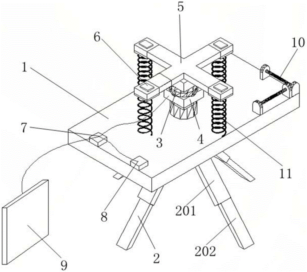
[0017] Such as figure 1 As shown, the mechanical failure debugging device for rotorcraft includes a base 1, the base 1 is supported by a telescopic tripod 2, and a spherical universal joint 3 is installed on the upper surface of the base 1, and the The spherical universal joint 3 is connected with an encoder 4 for obtaining the three-dimensional attitude data of the spherical universal joint 3, and the spherical universal joint 3 is equipped with a force arm fixing frame 5, and the force arm quantity of the force arm fixing frame 5 is the same as The rotor support quantity of rotorcraft is corresponding, and pressure sensor 6 is all installed on described each arm of force, when rotorcraft is installed on the arm fixed frame 5, described pressure sensor 6 is positioned at the arm of force and the rotor support of rotorcraft The room is used...


PUM


Abstract

The invention discloses a mechanical failure debugging device for a rotor craft. According to the device, the debugging effect can be improved. The debugging device comprises a base, wherein the base is supported through a telescopic support, a spherical surface cardan joint is installed on the upper surface of the base, an encoder is connected to the spherical surface cardan joint, the spherical surface cardan joint is provided with a moment arm fixing rack, and a pressure sensor is installed on each moment arm. The debugging device further comprises a controlling and processing chip, a remote control signal adaptor and a display device. By the adoption of the debugging device, detection of the direction and distance of each path of signal of a remote controller can be realized, whether a sensor or a rotor wing of the rotor craft works normally can be detected, whether the axis of rotation of the rotor wing is overlarge can be detected preliminarily, further debugging can be conducted on a control system of the craft according to detection results, the influence of mechanical installation errors on rotor craft control accuracy is reduced, and the debugging effect is good. The debugging device is suitable for being popularized and applied in the field of craft debugging equipment.

Description

technical field [0001] The invention belongs to the field of aircraft debugging equipment, and in particular relates to a mechanical fault debugging device for a rotorcraft. Background technique [0002] A quadrotor is an unmanned aerial vehicle with four rotors (propellers). The four rotors have a cross-shaped or X-shaped cross structure, and the two opposing rotors form a group with the same rotation direction; different groups of rotors have different rotation directions. Different from traditional helicopters, quadrotors can only achieve various actions by changing the speed of the rotor (propeller). It can realize flight actions such as vertical take-off and landing, hovering, advance and retreat, etc. It has the characteristics of simple mechanical structure, high space flexibility, simple control, and good autonomy. Inspection and other fields have broad application prospects, and it is the frontier field of intelligent robot research in recent years. [0003] Quad...

Claims


Application Information

Patent Timeline
Patent Type & Authority Applications(China)
IPC IPC(8): G05B23/02
Inventor 王晓东马磊韦宗毅张景鑫
Owner SOUTHWEST JIAOTONG UNIV
Learn More