A current sharing method for a charger

A technology of chargers and current parameters, applied in current collectors, electric vehicles, electrical components, etc., can solve the problems of unbalanced output current of the chopper, thermal stress of the chopper, damage to the power device of the chopper, etc. The flow effect is stable and reliable, the flow sharing control is simple, and the calculation amount is small.

Active Publication Date: 2016-04-20
SHENZHEN KSTAR SCI & TECH
View PDF2 Cites 0 Cited by
  • Summary
  • Abstract
  • Description
  • Claims
  • Application Information

AI Technical Summary

Problems solved by technology

The former needs to use large-capacity power devices such as IGBT, and the cost of the device itself and the radiator is relatively high, so the latter is often used in general products, that is, multiple choppers are used for power supply; when multiple choppers are running, Even if the power devices of each chopper receive the same switching signal, the output current between the choppers will be unbalanced due to the different internal resistances of the choppers; when the load power is large, the uneven current may It will cause the chopper with a large current to heat up or the stress will exceed the standard, and then damage the power device of the chopper

Method used


Image

  • A current sharing method for a charger
  • A current sharing method for a charger

Examples


Embodiment 1

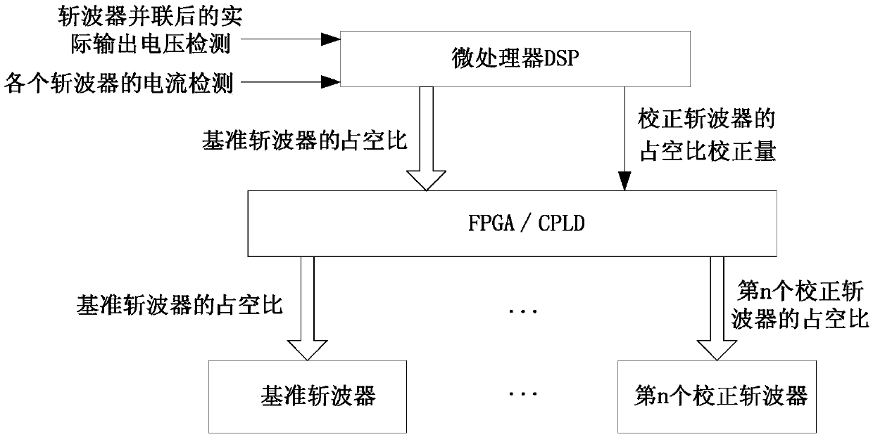
[0022] Such as figure 1 As shown, this example provides a current sharing method for a charger, including: a microprocessor DSP, an FPGA module, and at least two choppers, the choppers are connected in parallel, and the microprocessor DSP respectively detects all the choppers The actual output voltage of the choppers connected in parallel and the output current of each chopper; wherein, the microprocessor DSP drives a chopper through a PWM port, and the chopper driven by the microprocessor DSP is the reference chopper; the remaining choppers are driven by the FPGA module, and the chopper driven by the FPGA module is a correction chopper; after the microprocessor DSP collects the total actual output voltage of all choppers connected in parallel , compare the actual output voltage with the preset charging voltage value, adjust the duty cycle of the reference chopper until the actual output voltage matches the preset charging voltage value, and obtain that the reference chopper ...

Embodiment 2

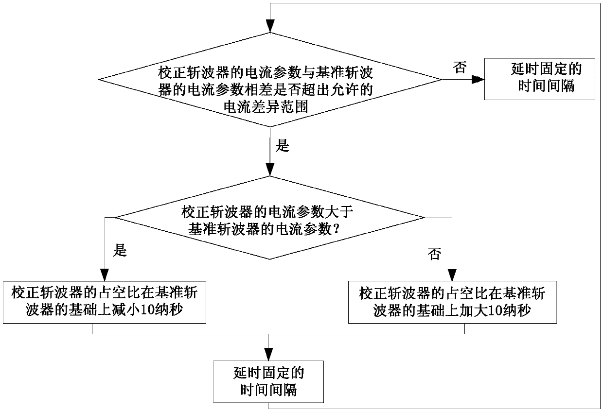
[0031] On the basis of Example 1, this example compares the current parameters of the reference chopper and the current parameters of the corrected chopper. When the current error between the two is greater than the allowable current difference, if the current parameter of the corrected chopper Greater than the current parameter of the reference chopper, then the duty ratio of the correction chopper is reduced according to the set duty ratio adjustment amount; if the current parameter of the correction chopper is less than the current parameter of the reference chopper , then the duty ratio of the correction chopper is increased according to the set duty ratio adjustment amount; after a fixed time interval, return to the current parameter of the reference chopper and the current parameter of the correction chopper Compare and loop accordingly. The workflow diagram of this example is as follows figure 2 As shown, when the current error between the two is less than the allowab...

Embodiment 3

[0039] On the basis of Embodiment 1 or Embodiment 2, in this example, a UPS takes power from the bus through the BUCK circuit and charges the battery. Since the UPS is a system with N wires, the chargers are divided into two groups, the positive group charger and the negative group charger. Both the positive group charger and the negative group charger have two chargers composed of BUCK circuits, named respectively A positive group charger, a second positive group charger, a first negative group charger and a second negative group charger, when the charger is running, the PWM ports of the first positive group charger and the first negative group charger drive After being calculated by the microprocessor DSP, it is sent through a PWM port of the microprocessor DSP, and the PWM port drive of the second positive group charger and the second negative group charger is carried out by the correction method described in embodiment 1 or embodiment 2 Correction, the correction value is ...


PUM


Abstract

The invention provides a charger current sharing method. A microprocessor DSP, an FPGA module and at least two choppers are included, the microprocessor DSP is used for respectively detecting the actual output voltage of all the choppers in parallel connection and the output current of each chopper, and is used for driving a benchmark chopper through a PWM port, the rest of the choppers are correction choppers and are driven by the FPGA module, the microprocessor DSP is used for is used for comparing the actual output voltage and a preset charging voltage value to obtain the benchmark duty ratio of the benchmark chopper at the moment, and correcting values of all the correction choppers are obtained through current parameters of the benchmark chopper and current parameters of the correction choppers. According to the charger current sharing method, only one PSW port of the microprocessor DSP is used for driving the benchmark chopper, the rest of the correction choppers are driven by an FPGA, current sharing control among the choppers is easy, the calculated amount is small, and the effect is stable and reliable.

Description

technical field [0001] The invention relates to a current sharing method, in particular to a current sharing method of a charger. Background technique [0002] In power electronic equipment such as high-voltage DC power supplies, electric vehicle charging piles, and UPS, DC-DC voltage conversion circuits called choppers or switching power supplies are required to supply power to DC loads; when the load power is large, more Two DC conversion circuits are connected in parallel to output power to realize a low-cost and high-efficiency power supply solution. However, in UPS and other equipment, the PWM wave generating unit of DSP is occupied by other power electronic circuits such as rectification. In the parallel connection of multiple choppers In this case, there may be insufficient PWM resources. [0003] In the case of supplying power to a high-power DC load, a single chopper or multiple choppers are usually used for power supply. The former needs to use large-capacity pow...

Claims


Application Information

Patent Timeline
Patent Type & Authority Patents(China)
IPC IPC(8): H02J7/00
Inventor 刘程宇王屹万学维
Owner SHENZHEN KSTAR SCI & TECH
Why Eureka
Try Eureka