A z-source inverter circuit

An inverter circuit and circuit technology, which is applied in the direction of electrical components, AC power input conversion to DC power output, output power conversion devices, etc., can solve the problems of starting shock and excessive stress of devices, and achieve the effect of avoiding burning equipment

Inactive Publication Date: 2016-05-11
UNIV OF ELECTRONICS SCI & TECH OF CHINA
View PDF5 Cites 0 Cited by
  • Summary
  • Abstract
  • Description
  • Claims
  • Application Information

AI Technical Summary

Problems solved by technology

[0006] The beneficial effect of the present invention is that it can effectively solve the problems of system start-up impact and excessive device stress, and at the same time, the output power of the inverter circuit can be adjusted in a wide range and effectively. When the upper and lower bridge arms of the inverter circuit are simultaneously conducted When (that is, the bridge arm is straight-through), it can protect the system from burning the device due to a short circuit

Method used


Image

  • A z-source inverter circuit
  • A z-source inverter circuit
  • A z-source inverter circuit

Examples


Embodiment Construction

[0016] The technical solutions of the present invention will be described in detail below with reference to the accompanying drawings.

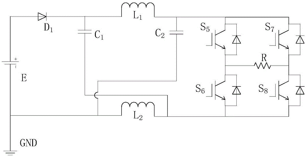
[0017] The Z source inverter circuit of the present invention, such as Figure 4 As shown, it includes a Z source network and a single-phase inverter circuit. The Z source network is composed of diodes D1, D2, inductors L1, L2, capacitors C1, C2, IGBT tubes S1, S2, S3, and S4; among them, the drain of S1 Connect the positive pole of the power supply E, its source is connected to the negative pole of the diode D1; the source of S1 is connected to the drain of S2 through the inductor L1; the source of S1 is connected to the drain of S3 and S4 through the inductor L1, diode D2 and capacitor C2 in turn The anode of diode D1 is connected to the cathode of power supply E, the anode of diode D1 is connected to the source of S1 through inductor L2 and capacitor C1 in turn; the anode of diode D1 is connected to the source of S3; the source of S2 is co...


PUM


Abstract

The invention relates to the electronic circuit technology, in particular to a Z-source inverter circuit. The Z-source inverter circuit comprises a Z-source network and a single phase inverter circuit. The Z-source inverter circuit is characterized in that the Z-source network is composed of a diode D1, a diode D2, an inductor L1, an inductor L2, a capacitor C1, a capacitor C2, an IGBT transistor S1, an IGBT transistor S2, an IGBT transistor S3 and an IGBT transistor S4. The drain electrode of the S1 is connected with the positive electrode of a power source E, and the source electrode of the S1 is connected with the negative electrode of the diode D1. The source electrode of the S1 passes through the inductor L1 and then is connected with the drain electrode of the S2. The source electrode of the S1 sequentially passes through the inductor L1, the diode D2 and the capacitor C2 and then is connected with the drain electrode of the S3 and the drain electrode of the S4. The positive electrode of the diode D1 is connected with the negative electrode of the power source E, and the positive electrode of the diode D1 sequentially passes through the inductor L2 and the capacitor C1 and then is connected with the source electrode of the S1. The positive electrode of the diode D1 is connected with the source electrode of the S3. The Z-source inverter circuit has the advantages that the starting impact problem and the overlarge device stress problem of the system can be effectively solved, and meanwhile wide-range and effective adjusting can be conducted on the output power of the inverter circuit. The Z-source inverter circuit is particularly suitable for Z-source inverter circuits.

Description

technical field [0001] The invention belongs to electronic circuit technology, and specifically relates to a Z-source inverter circuit. Background technique [0002] Inverter circuit is a circuit that converts DC electric energy (battery, storage battery or energy source similar to DC power supply, such as electricity similar to DC generated by rectification of alternating current) into alternating current, and is widely used in industry. Inverter circuits can be used to form various AC power sources. Among the existing power sources, batteries, dry cells, solar cells, etc. are all DC power sources. When these power sources are required to supply power to an AC load, an inverter circuit is required. In addition, inverter devices are used in power electronic devices such as frequency converters for AC motor speed regulation, uninterruptible power supplies, induction heating power supplies, and photovoltaic power generation systems. [0003] Currently widely used inverters ba...

Claims


Application Information

Patent Timeline
Patent Type & Authority Patents(China)
IPC IPC(8): H02M7/5387H02M1/32
Inventor 毕闯向勇侯鹏胡金刚
Owner UNIV OF ELECTRONICS SCI & TECH OF CHINA
Why Eureka
Try Eureka