
Adjacent region interference determination method and device

A technology of adjacent cell interference and determination method, applied in the direction of electrical components, wireless communication, etc., can solve the problems of affecting the accuracy of interference adjacent cells, the inability of the base station to determine the interference adjacent cells in time, and the high complexity of the implementation of the interference adjacent cells. complexity, improve accuracy, and achieve the effect of centralized management and maintenance

Inactive Publication Date: 2014-08-13
CHINA ACAD OF TELECOMM TECH
View PDF5 Cites 1 Cited by
  • Summary
  • Abstract
  • Description
  • Claims
  • Application Information

AI Technical Summary

Problems solved by technology

[0005] When the base station is powered on, there is no UE access, and the UE cannot be triggered to perform neighbor cell measurement, and the UE triggers and reports the measurement results according to conditions. Therefore, the base station cannot determine the interfering neighboring cell in time, which affects the accuracy of determining the interfering neighboring cell.
When there are UEs reporting measurement results, there may be multiple UEs reporting measurement results. Each UE reports different measurement results for the same neighboring cell. The implementation complexity of determining the interfering neighboring cell by the base station based on the measurement results of multiple UEs is relatively high.

Method used


Image

  • Adjacent region interference determination method and device
  • Adjacent region interference determination method and device
  • Adjacent region interference determination method and device

Examples


Embodiment Construction

[0138] Before describing the technical solutions provided by the present invention through specific embodiments, some technical features involved in the embodiments of the present invention will be explained first.

[0139] A centralized node can be a logical entity or an independent device. For example, it may be a core network device such as an independent gateway (GW), or a software or hardware module set on a core network device such as a GW, may be a core network node, or may be an operation, management and maintenance (Operation Administration and Maintenance, OAM ) node, may also be a software or hardware module set at the OAM node, may be a base station, or may be a software or hardware module set at the base station. A centralized node can control multiple base stations.

[0140] Base station, in the embodiment of the present invention, the base station refers to a small station with an omnidirectional antenna, such as a low power node (Low Power Node, LPN), such as ...


PUM


Abstract

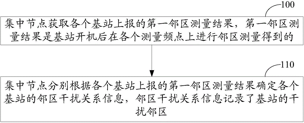
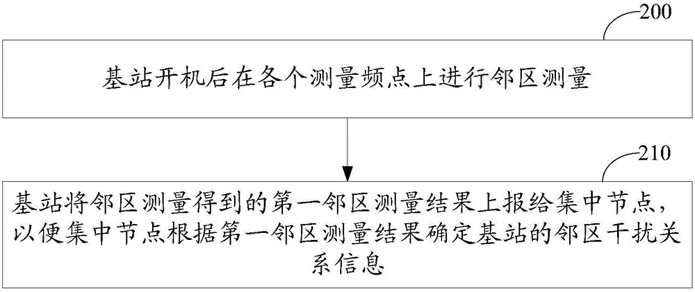
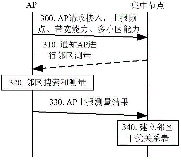
The invention discloses an adjacent region interference determination method and device. The method comprises the steps that a centralized node obtains a first adjacent region measurement result reported by each base station, wherein each first adjacent region measurement result is obtained by conducting adjacent region measurement on each measurement frequency point after the corresponding base station is started up; the centralized node determines adjacent region interference relation information of each base station according to the first adjacent region measurement result reported by each base station, wherein the adjacent region interference relation information records interference adjacent regions of the base stations. Due to the fact that the base stations, instead of UE, directly conduct adjacent region measurement, the interference adjacent regions can be determined in time, and accuracy of determining the interference adjacent regions is improved. Due to the fact that the base stations directly conduct adjacent region measurement, the phenomenon that a plurality of pieces of UE report different measurement results for the same adjacent region can be avoided, and the implementation complexity for determining the interference adjacent regions is reduced; in addition, the adjacent region interference relation of each base station is determined by the centralized node, and centralized management and maintenance of the adjacent region interference relations are achieved.

Description

technical field [0001] The present invention relates to the technical field of wireless communication, in particular to a method and a device for determining adjacent cell interference. Background technique [0002] In a wireless communication system, signals propagate through the wireless environment. Multiple access points, such as base stations in a cellular network and access points (Access Points, APs) in a wireless local area network (Wireless Local Area Network, WLAN) system, are deployed. If adjacent access points use the same operating frequency, in most systems, such as Orthogonal Frequency Division Multiplexing (OFDM) systems and Code Division Multiple Access (CDMA) systems, it will cause Adjacent cells interfere, resulting in ineffective use of spectrum resources and degrading wireless system transmission performance. [0003] The interference coordination technology in the current Long Term Evolution (LTE) system includes Inter-cell Interference Coordination (I...

Claims


Application Information

Patent Timeline
IPC IPC(8): H04W24/08H04W24/10
Inventor 贺媛谌丽秦飞
Owner CHINA ACAD OF TELECOMM TECH
Learn More