Method for contactless measurement of relative positions by means of Hall sensors

A relative position, non-contact technology, applied in the field of displacement sensor, can solve the problems of error, unwanted change, insensitive signal processing operation, etc.

Active Publication Date: 2017-03-01
TE CONNECTIVITY GERMANY GMBH
View PDF9 Cites 0 Cited by
  • Summary
  • Abstract
  • Description
  • Claims
  • Application Information

AI Technical Summary

Problems solved by technology

[0011] However, these known methods have the disadvantage that the distance between the permanent magnet and the magnetic sensor constitutes a significant source of error in the measurement
[0018] However, this is unacceptable for very sensitive systems, such as, for example, auxiliary steering systems or pedal travel measurement in motor vehicles, so there is less sensitivity to unwanted changes in the spacing between the permanent magnet and the Hall sensor element The need for improved signal processing operations

Method used


Image

  • Method for contactless measurement of relative positions by means of Hall sensors
  • Method for contactless measurement of relative positions by means of Hall sensors
  • Method for contactless measurement of relative positions by means of Hall sensors

Examples


Embodiment Construction

[0042] First refer to the following Figure 6 and figure 1 The present invention will be described in more detail.

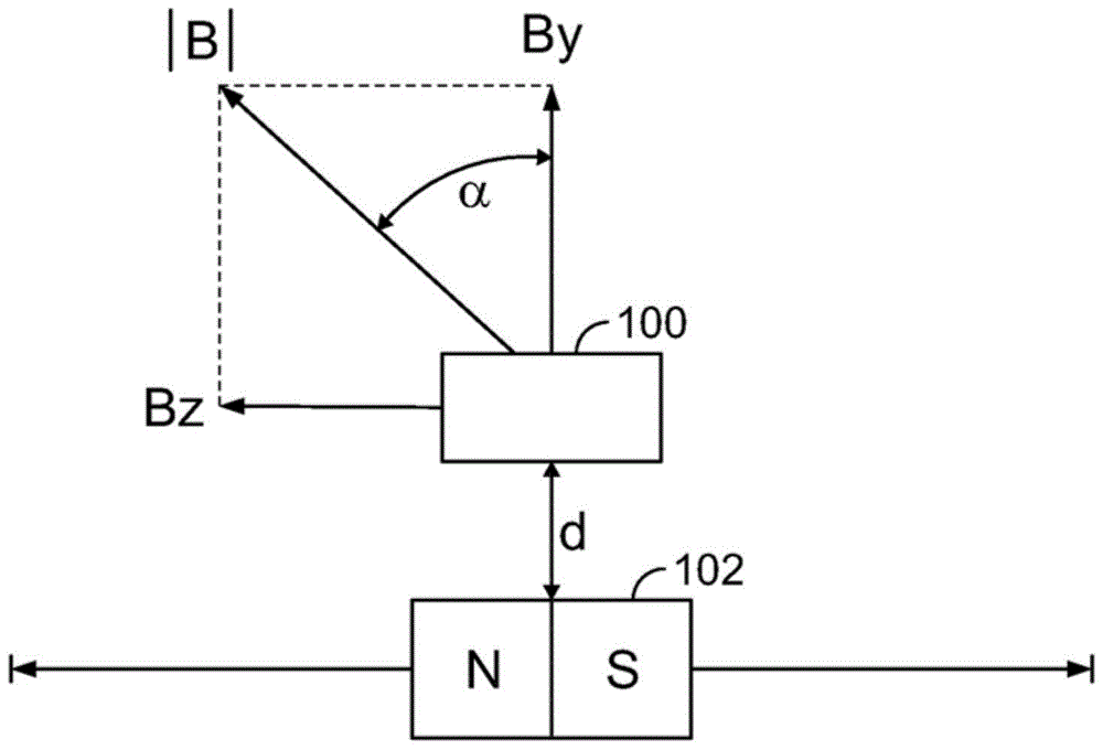
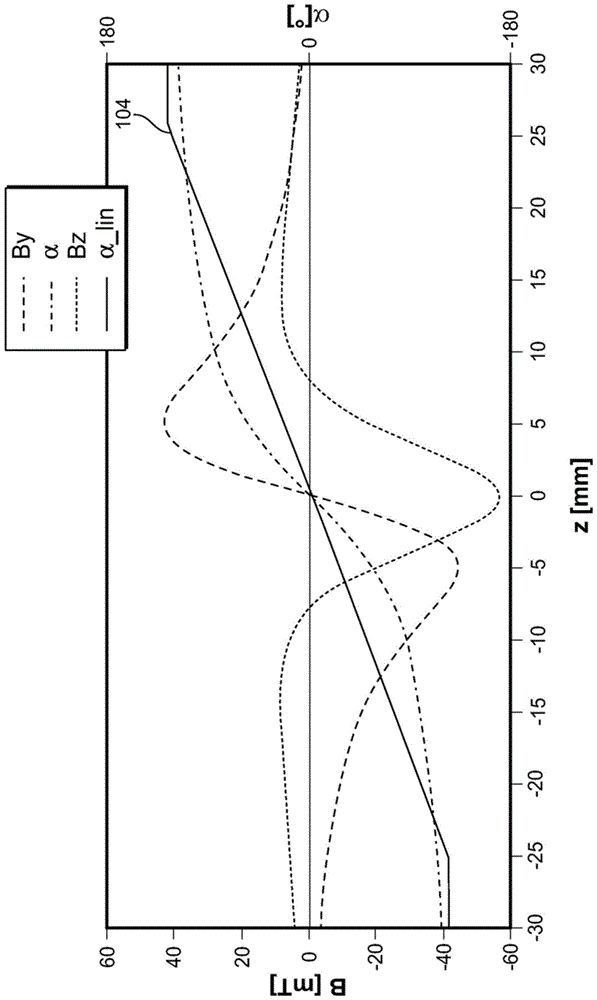
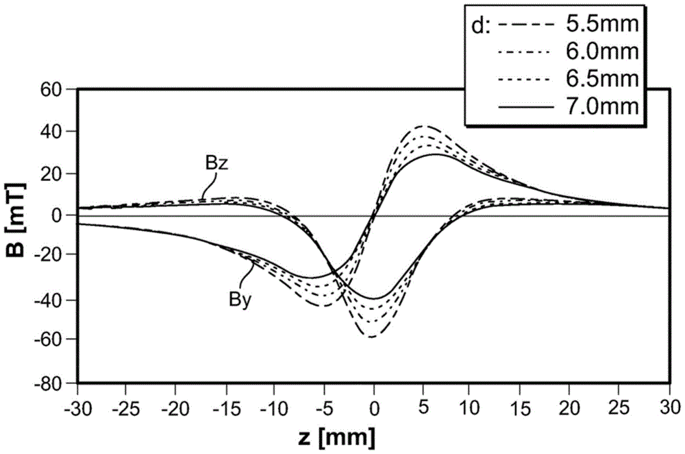
[0043] The displacement sensor arrangement according to the first embodiment is shown in figure 1 middle. The hall sensor 100 is installed to be fixed in position, and the permanent magnet 102 is supported to be linearly movable relative to the hall sensor 100 . The permanent magnet 102 has a pole configuration such that its south / north axis is oriented parallel to the direction of motion. In principle, however, the principles of the invention can also be used for arrangements in which the permanent magnets 102 have such a pole configuration that their south / north axes extend transversely with respect to the direction of motion. The permanent magnet 102 can be moved in two directions from the figure 1The zero position of is shifted outwards by about 25mm, for example. The Hall sensor 100 detects at least two orthogonal magnetic field components - one exten...


PUM


Abstract

The invention relates to a method for contactless measurement of the relative positions of a magnetic field generating source (102) and a magnetic field sensor (100) relative to each other. The invention also further relates to a corresponding displacement sensor. According to the invention, a magnetic field sensor (100) detects at least two spatial components (Bz, By) of the magnetic field and generates a position signal from the measured components. The method comprises the steps of: calculating a position signal based on the quotient of two magnetic field components; and correcting the magnetic field component extending in the direction of motion between the magnetic field source (102) and the magnetic field sensor (100) before calculating the quotient value.

Description

technical field [0001] The invention relates to a method for non-contact measurement of the relative positions of a magnetic field generating magnetic field source and a magnetic field sensor relative to each other. Furthermore, the present invention also relates to a corresponding displacement sensor. Background technique [0002] In particular, it is intended to detect and estimate linear motions in a contactless manner by means of the method according to the invention by means of magnetic interactions between one or more permanent magnets and a Hall effect-based magnetic sensor. [0003] The measurement of linear motion is used, for example, in the control of machine tools, pneumatics, automation and robotics, and in the automotive sector. Non-contact motion detection offers the advantage of being free from wear and tear over others. Among non-contact measurement methods, optical and magnetic methods are the most common. While optical methods guarantee a very high leve...

Claims


Application Information

Patent Timeline
Patent Type & Authority Patents(China)
IPC IPC(8): G01D5/14G01D5/244
CPCG01D5/145G01D5/2448G01B7/14G01R33/07
Inventor O.沙夫
Owner TE CONNECTIVITY GERMANY GMBH
Why Eureka
Try Eureka