Gas-liquid two-phase mist generator and generation method thereof

A generator and fine mist technology, applied in the direction of chemical instruments and methods, mixing methods, dissolution, etc., can solve the problems of high water quality requirements, small load area, easy to block nozzles, etc., achieve uniform atomization distribution, increase fog The effect of reducing the area and reducing the size of the fog particles

Inactive Publication Date: 2014-08-20
HUZHOU TEACHERS COLLEGE
View PDF6 Cites 3 Cited by
  • Summary
  • Abstract
  • Description
  • Claims
  • Application Information

AI Technical Summary

Problems solved by technology

The existing factory humidifiers mainly include: 1) The high-pressure micro-mist humidifier disclosed in Chinese patent 202188576U, the diameter of mist particles is 3-15??m, the energy consumption is 6W / kg, and the load area is 100-15000M 2 , but it is easy to block the nozzle; 2) For example, the industrial ultrasonic humidifier disclosed in Chinese patent 202835639U, the mist particle diameter is 1-5??m, the energy consumption is 10W / kg, and the load is 10-1000M 2 , but the load area of ​​a single unit is small and has high requirements for water quality; 3) For example, the evaporative wet film humidifier disclosed in Chinese patent 202955812U does not spray, energy consumption is 11W / kg, and the load is 10-1000M 2, However, the air supply distance is short; the above three industrial humidifiers are not mixed with gas, and they are all directly atomized with liquid as the medium
There is also a type of two-fluid spray humidifier disclosed in Chinese patent 202391459U, with a mist particle diameter of 8.47-25??m, energy consumption of 5-22 liters / min / kg, and a load of 10-300M 2 , the power consumption is large, although the gas-liquid mixing type is used, but only one mixing, the particles are larger
It is comprehensively known that in order to achieve the atomization effect, there are some problems in terms of humidification cost and humidification effect.

Method used


Image

  • Gas-liquid two-phase mist generator and generation method thereof
  • Gas-liquid two-phase mist generator and generation method thereof
  • Gas-liquid two-phase mist generator and generation method thereof

Examples


Embodiment 1

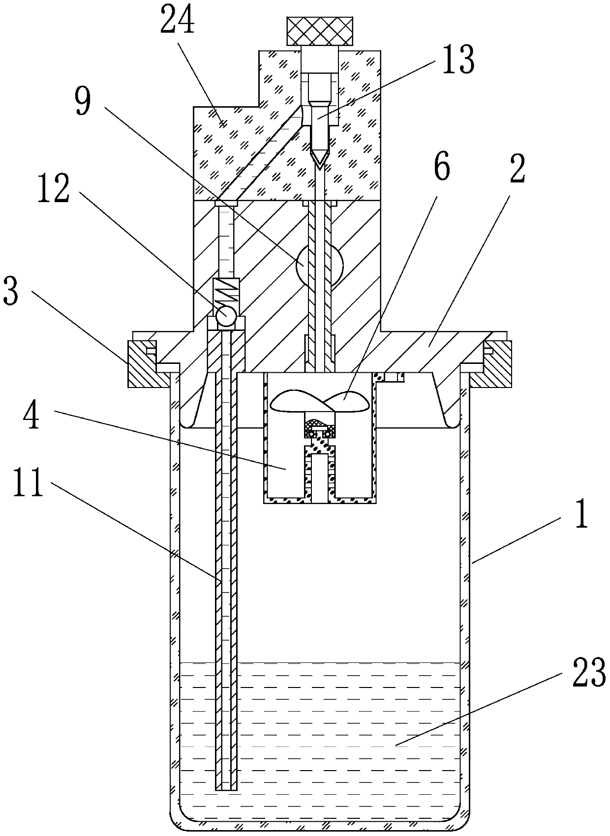
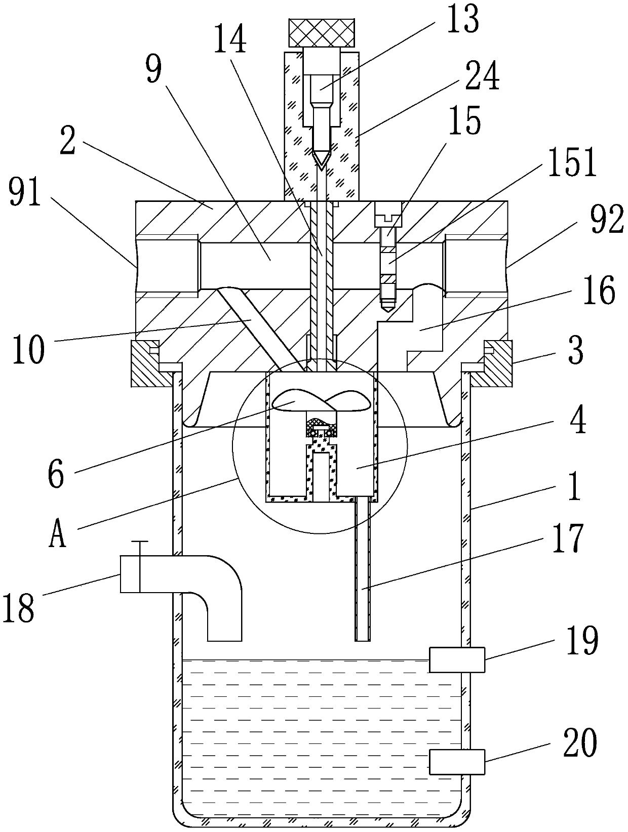
[0025] Embodiment 1: as figure 1 , 2 As shown, a gas-liquid two-phase fine mist generator includes a liquid storage tank 1 and a valve cover 2 sealed on the upper end of the liquid storage tank 1, and a clamping sleeve 3 is fastened at the connection between the liquid storage tank and the valve cover , the lower end of the clamping sleeve 3 is in interference fit with the upper edge of the liquid storage tank 1 , and the upper end of the clamping sleeve 3 is in interference fit with the edge of the valve cover 2 . The upper part of the side wall of the liquid storage tank 1 has a liquid filling port 18, and the lower part of the side wall of the liquid storage tank is equipped with an upper liquid level sensor 19 and a lower liquid level sensor 20 at longitudinal intervals, and the upper liquid level sensor 19 and the lower liquid level sensor 20 pass through The controller is connected with the liquid filling port 18 . An air guide channel 9 runs through the valve cover 2 ...

Embodiment 2

[0028] Embodiment 2: The structure of this embodiment is basically the same as that of Embodiment 1, the difference is that, as Figure 4 As shown, the bottom surface of the primary atomization chamber 4 is a guiding slope 25 , and the guiding slope 25 is inclined towards the mouth of the liquid return pipe 17 . The bottom surface of the primary atomization chamber is a guiding slope. Since the guiding slope is inclined towards the mouth of the liquid return pipe, the non-atomized liquid produced in the primary spraying chamber is kept toward the liquid return pipe along the guiding slope, which is convenient for the primary fog The liquid in the atomization chamber is discharged to avoid residual liquid in the primary atomization chamber.

Embodiment 3

[0029] Embodiment 3: The structure of this embodiment is basically the same as that of Embodiment 1, the difference is that, as Figure 5 As shown, the center of the breaking wheel 6 is integrally connected with a top 21. The top 21 is conical. The needle valve and the drip tube 14 are all coaxial.

[0030] Set the top at the axis of the breaking wheel, and the top is vertically corresponding to the adjusting needle valve. After the adjusting needle valve adjusts the liquid entering the oil suction pipe into liquid droplets, the liquid drops vertically on the top of the rotating breaking wheel. The tip, the tip of the tip penetrates the droplet and splits the droplet into several water petals. The water petals are broken up by the breaking wheel, and the droplet is split by the top, and then broken up by the breaking wheel, so that the droplet can achieve Split and disperse for many times, so that the mist particles of the atomized liquid are finer, and the liquid and gas are...


PUM


Abstract

The invention relates to a humidifier, and in particular to a gas-liquid two-phase mist generator and a generation method thereof. The gas-liquid mist generator comprises a liquid storage tank; the upper end of the liquid storage tank is sealed with a valve cover, and a gas guiding channel horizontally penetrates through the valve cover; the lower end surface of the valve cover is provided with a first atomizing chamber and an oil suction pipe inserted into the liquid storage tank; an input end of the gas guiding channel is communicated with the first atomizing chamber through an inclined hole; the chamber of the liquid storage tank is communicated with an output end of the gas guiding channel; scattering wheels are horizontally arranged in the first atomizing chamber; the top of the valve cover is provided with a regulating needle valve; the oil suction pipe is communicated with an inlet of the regulating needle valve; an outlet of the regulating needle valve vertically corresponds to the first atomizing chamber; and the first atomizing chamber through an outlet of the first atomizing chamber is communicated with the liquid storage tank. The invention can effectively mix gas and liquid and realize two times of mixing, and has the beneficial effects of good atomizing distribution uniformity, simple structure and no blocking.

Description

technical field [0001] The invention relates to a humidifier, in particular to a gas-liquid two-phase fine mist generator and a generating method thereof. Background technique [0002] In modern industrial production and scientific experiments, the emphasis on air humidity is increasing day by day, and the requirements are getting higher and higher. If the humidity cannot meet the requirements, it will cause different degrees of adverse consequences, such as "electrostatic bombardment" in electronic component factories. , Deformation, adhesion, etc. in textile printing and dyeing factories. The existing factory humidifiers mainly include: 1) The high-pressure micro-mist humidifier disclosed in Chinese patent 202188576U, the diameter of mist particles is 3-15??m, the energy consumption is 6W / kg, and the load area is 100-15000M 2 , but it is easy to block the nozzle; 2) For example, the industrial ultrasonic humidifier disclosed in Chinese patent 202835639U, the mist particle...

Claims


Application Information

Patent Timeline
Patent Type & Authority Applications(China)
IPC IPC(8): B01F13/06B01F3/04
Inventor 徐云杰戴朝卿
Owner HUZHOU TEACHERS COLLEGE
Why Eureka
Try Eureka