Punching die

A mold and punching technology, applied in the direction of punching tools, forming tools, manufacturing tools, etc., to achieve the effect of improving efficiency

Inactive Publication Date: 2014-08-20
昆山电子羽电业制品有限公司
View PDF5 Cites 4 Cited by
  • Summary
  • Abstract
  • Description
  • Claims
  • Application Information

AI Technical Summary

Problems solved by technology

Existing punching dies also need a special flanging die to flang the workpiece after the punching is completed

Method used


Image

  • Punching die

Examples


Embodiment Construction

[0015] The present invention will be described in detail below in conjunction with the accompanying drawings.

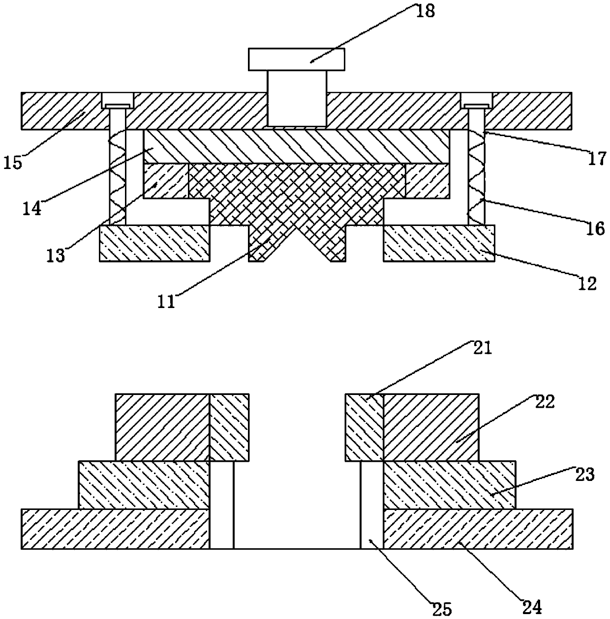
[0016] see figure 1 , a punching die of the present embodiment includes an upper die set and a lower die set, the upper die set is located above the lower die set, a first driving device 18 is connected above the upper die set, and the upper die set includes a punch 11, The punch 11 includes a punch body, and the middle part of the lower surface of the punch body protrudes downwards to form a punch block; Compatible first through hole, the first through hole is compatible with the punch body, the die sleeve 21 is provided with a second through hole adapted to the punch block, and the bottom of the die sleeve 21 is connected with the second driving device 25.

[0017] In this embodiment, the die cover 21 is placed in the first through hole, the upper surface of the die cover 21 is flush with the upper surface of the die body 22, the workpiece is placed on the die bo...


PUM


Abstract

The invention discloses a punching die which comprises an upper die assembly and a lower die assembly. The upper die assembly is located above the lower die assembly, the upper portion of the upper die assembly is connected with a first driving device, the upper die assembly comprises a puncher pin which comprises a punch body, and the middle portion of the lower surface of the punch body protrudes downwards to form a punch insert. The lower die assembly comprises a female die body and a female die sleeve, the female die body is provided with a first through hole which is matched with the female die sleeve, the first through hole is matched with the punch body, the female die sleeve is provided with a second through hole matched with the punch insert, and the lower portion of the female die sleeve is connected with a second driving device. The punching die completes flanging on a hole while punching a workpiece and improves efficiency, different female die sleeves and different puncher pins can be replaced according to needs of punching sizes, and multiple purposes are achieved through one die.

Description

technical field [0001] The invention relates to a mold, in particular to a punching mold. Background technique [0002] Mold, various molds and tools used in industrial production for injection molding, blow molding, extrusion, die-casting or forging forming, smelting, stamping, stretching and other methods to obtain the required products. In short, a mold is a tool used to shape an object. This tool is composed of various parts, and different molds are composed of different parts. It mainly realizes the processing of the shape of the article through the change of the physical state of the formed material. Punching refers to punching various graphics on steel plates, leather, cloth, wood and other materials to meet different needs, specifically: cross holes, diamond holes, fish scale holes, eight-character holes, hexagonal holes, punching plates, long holes , Square holes, round holes, perforated sheet metal, triangular holes and so on. [0003] As we all know, a punching...

Claims


Application Information

Patent Timeline
Patent Type & Authority Applications(China)
IPC IPC(8): B21D37/10B21D28/34B21D35/00B21D45/08
Inventor 李国新
Owner 昆山电子羽电业制品有限公司
Why Eureka
Try Eureka