
An automatic high-speed metal pipe cutting machine

A technology for metal pipes and cutting machines, which is applied in the direction of metal processing equipment, pipe shearing devices, and accessories of shearing machines, etc. It can solve the problems affecting the surface smoothness and shearing accuracy of the cut workpiece, rough cutting surface, and high cutting force, etc. problems, to achieve the effect of high man-machine work efficiency, easy operation and maintenance, and high cutting precision

Active Publication Date: 2016-08-17
东莞市晋诚机械有限公司
View PDF7 Cites 0 Cited by
  • Summary
  • Abstract
  • Description
  • Claims
  • Application Information

AI Technical Summary

Problems solved by technology

[0002] In the prior art, saw blade cutting and band saw blade cutting are used for pipe workpieces. Due to the shearing machine, knife collision occurs during work, the cutting speed is slow, the cost is high, the cutting force is large, the cutting surface is rough, and there are many burrs, which affect the cutting. The smoothness and shearing accuracy of the workpiece surface, in addition, the vibration is large, the noise is large, and there are many irons. Moreover, different shearing machines or mechanical adjustments are often used for different section widths, and the work efficiency is low.

Method used


Image

  • An automatic high-speed metal pipe cutting machine
  • An automatic high-speed metal pipe cutting machine
  • An automatic high-speed metal pipe cutting machine

Examples


Embodiment Construction

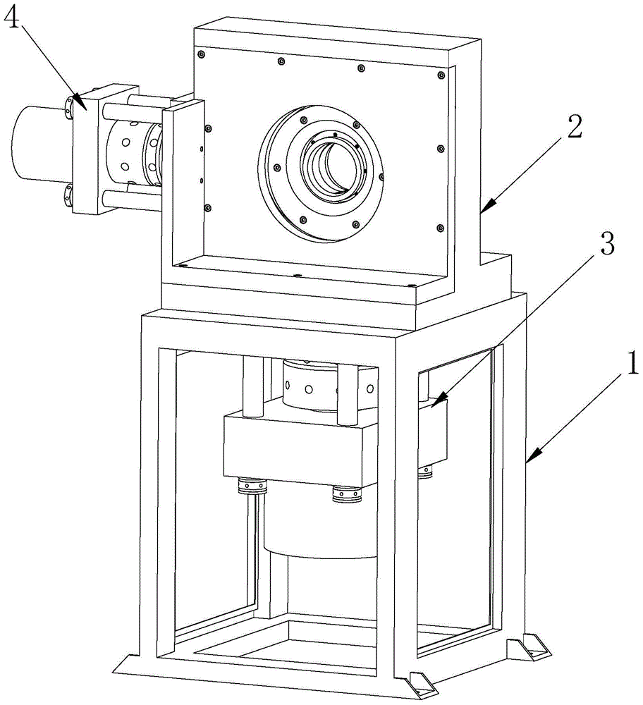
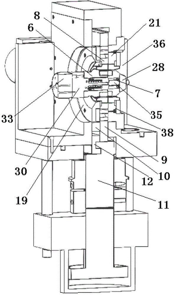
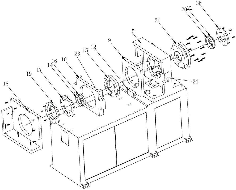
[0024] Such as Figure 1-5 As shown, an automatic high-speed metal pipe cutting machine described in the embodiment of the present invention includes a frame assembly 1 and a shear assembly 2, the bottom of the shear assembly 2 is provided with a lower hydraulic cylinder assembly 3, and the The side of the shearer assembly 2 is provided with a side hydraulic cylinder assembly 4, and the shearer assembly 2 includes a main base 5, and the main base 5 is provided with an inner floating knife assembly 6, an inner fixed knife assembly 7, and an outer floating knife assembly. Assembly 8 and outer fixed knife assembly 38, the inner floating knife assembly 6 is concentric with the outer floating knife assembly 8, the inner fixed knife assembly 7 is concentric with the outer fixed knife assembly 38, the inner floating knife assembly 6 and the inner fixed knife assembly 7 Constitute the inner knife assembly, the outer floating knife assembly 8 and the outer fixed knife assembly 38 const...


PUM


Abstract

The invention relates to an automatic high-speed metal tube cutting machine. The automatic high-speed metal tube cutting machine comprises a machine frame assembly and a shearing machine assembly. A lower hydraulic cylinder assembly is arranged at the bottom of the shearing machine assembly. A side hydraulic cylinder assembly is arranged on a side face of the shearing machine assembly. The shearing machine assembly comprises a main machine base, wherein an inner floating cutter assembly, an inner fixed cutter assembly, an outer floating cutter assembly and an outer fixing cutter assembly are arranged in the main machine base. The outer floating cutter assembly is sleeved with an upward-downward moving die and a leftward-rightward moving die, wherein the leftward-rightward moving die and the upward-downward moving die are tightly buckled, the lower surface of the upward-downward moving die is fixedly connected with a first piston rod of the lower hydraulic cylinder assembly, and a side face of the leftward-rightward moving die is fixedly connected with a second piston rod of the side hydraulic cylinder assembly. The automatic high-speed metal tube cutting machine has the advantages that no scrap iron exists, one time of cutting is completed within three seconds, noise is low, shearing accuracy is high, automatic cutting can be achieved, the automatic high-speed metal tube cutting machine is suitable for shearing workpieces with the fixed size and any lengths in batches, use is safe, man-machine work efficiency is high, the structure is firm, rigidity is high, vibration is small, the cutting size can be converted at a high speed, and operation and maintenance are easy and convenient.

Description

technical field [0001] The invention relates to an automatic high-speed metal pipe cutting machine. Background technique [0002] In the prior art, saw blade cutting and band saw blade cutting are used for pipe workpieces. Due to the shearing machine, knife collision occurs during work, the cutting speed is slow, the cost is high, the cutting force is large, the cutting surface is rough, and there are many burrs, which affect the cutting. The smoothness of the surface of the workpiece and the shearing accuracy, in addition, the vibration is large, the noise is large, and there are many irons. Moreover, different shearing machines or mechanical adjustments are often used for different section widths, and the work efficiency is low. Contents of the invention [0003] The purpose of the present invention is to provide an automatic high-speed metal pipe cutting machine to overcome the above-mentioned shortcomings in the current prior art. [0004] The purpose of the present i...

Claims


Application Information

Patent Timeline
Patent Type & Authority Patents(China)
IPC IPC(8): B23D21/00B23D33/00
Inventor 谢永福王南艳
Owner 东莞市晋诚机械有限公司
Learn More