Injection molding machine

An injection molding machine and pedestal technology, which is applied in the field of injection molding machines, can solve the problems of damaging the pedestal and the large force exerted by the pedestal for fixing the sliding parts, and achieves the effect of restraining the damage.

Active Publication Date: 2014-08-20
SUMITOMO HEAVY IND LTD
View PDF4 Cites 2 Cited by
  • Summary
  • Abstract
  • Description
  • Claims
  • Application Information

AI Technical Summary

Problems solved by technology

[0007] Conventionally, when a sliding member such as a movable platen deforms due to mold clamping force or thermal stress, a large force is applie

Method used


Image

  • Injection molding machine
  • Injection molding machine
  • Injection molding machine

Examples


Example

[0038] The first embodiment

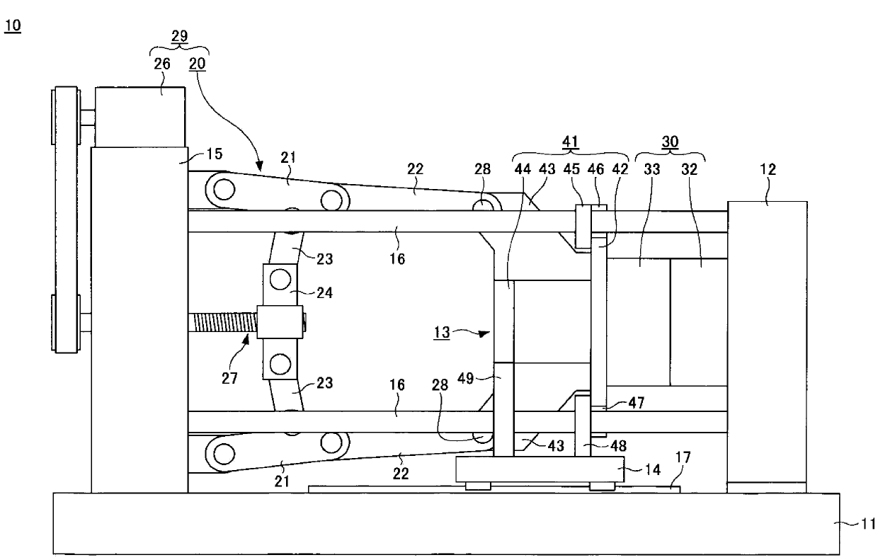
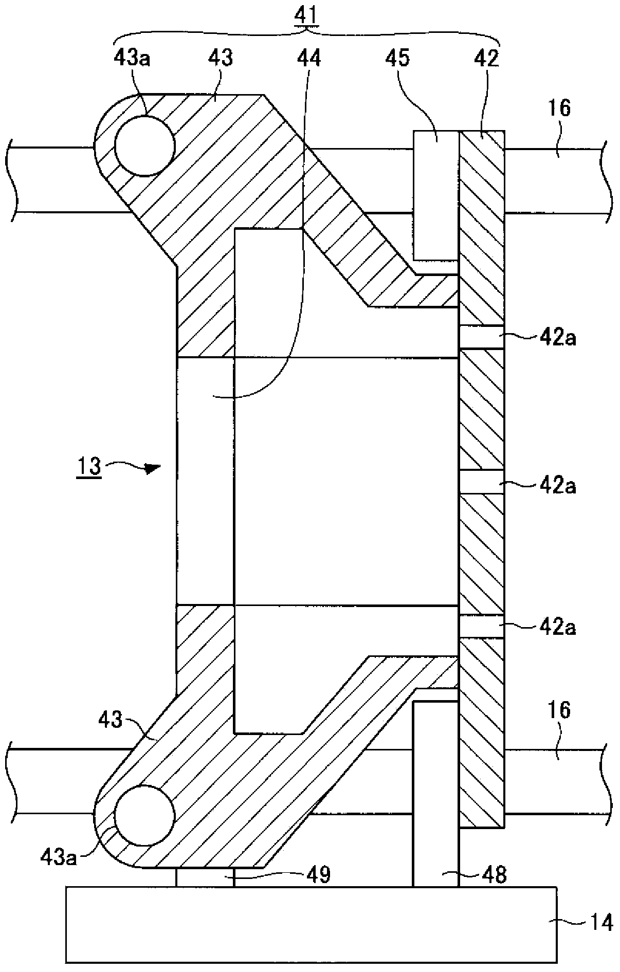
[0039] figure 1 It is a figure which shows the state when the mold closing of the injection molding machine of the 1st Embodiment of this invention is complete|finished. figure 2 It is a cross-sectional view showing the structure of the movable platen in the first embodiment of the present invention.

[0040] Such as figure 1 As shown, the injection molding machine 10 includes, for example, a frame 11, a fixed platen 12, a movable platen 13, a base 14, a back plate 15 as a support, a connecting rod 16, a guide 17, a toggle mechanism 20, a clamping motor 26, etc. .

[0041] The fixed pressing plate 12 may be fixed on the frame 11. The rear pressure plate 15 is arranged at an interval from the fixed pressure plate 12. The rear pressure plate 15 and the fixed pressure plate 12 are connected by a plurality of (for example, four) connecting rods 16. In order to allow the extension of the connecting rod 16 during mold clamping, the rear pressure plate 15 i...

Example

[0068] Second embodiment

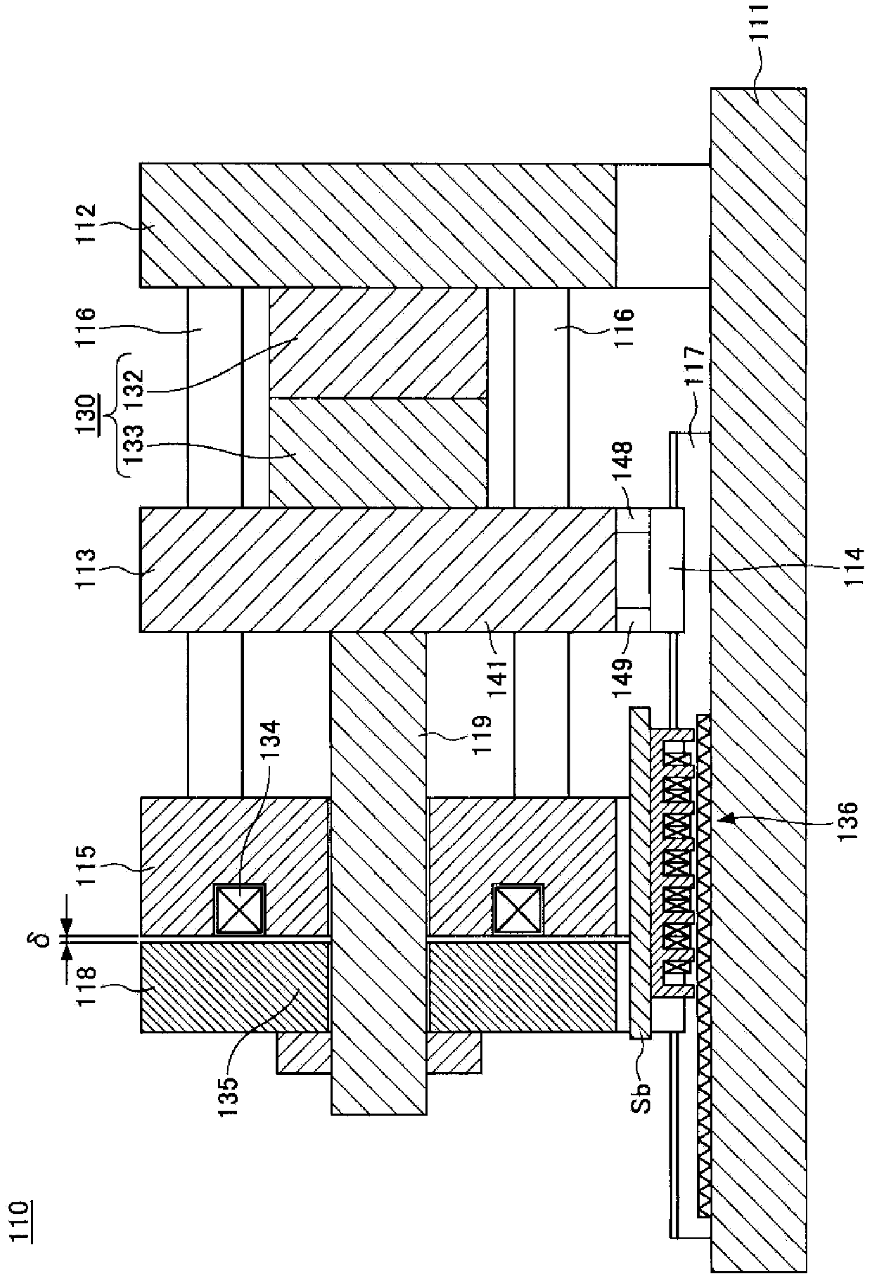
[0069] In the first embodiment, the toggle mechanism and the mold clamping motor 26 constitute a mold clamping force generation mechanism. In this embodiment, the electromagnet formed on the rear pressure plate and the suction portion formed on the suction plate constitute the clamping force generating mechanism.

[0070] image 3 It is a cross-sectional view showing the state of the injection molding machine of the second embodiment of the present invention when mold closing is completed. Such as image 3 As shown, the injection molding machine 110 includes, for example, a frame 111, a fixed pressing plate 112, a movable pressing plate 113, a base 114, a rear pressing plate 115, a connecting rod 116, a guide 117, a suction plate 118, a rod 119, and the like.

[0071] The rear pressing plate 115 may be fixed on the frame 111. The fixed pressing plate 112 is arranged at an interval from the rear pressing plate 115. The fixed pressing plate 112 and the r...


PUM


Abstract

An injection molding machine is provided, which includes: a frame; a guide provided on the frame; a block that is movable along the guide; and a slide member that moves together with the block, wherein the slide member includes a slide member body and a plurality of coupling portions, the coupling portions coupling the slide member body and the block, and the coupling portions are provided such that the coupling portions are apart from each other.

Description

technical field [0001] This application claims priority based on Japanese Patent Application No. 2013-027164 filed on February 14, 2013. The entire content of this application is incorporated in this specification by reference. [0002] The invention relates to an injection molding machine. Background technique [0003] Injection molding machines manufacture molded products by filling the cavity space of a mold unit with molten resin and solidifying it. The mold device is composed of a fixed mold and a movable mold. When the mold is closed, a cavity space is formed between the fixed mold and the movable mold. The molded product formed in the cavity space is ejected from the movable mold after the mold is opened (for example, refer to Patent Document 1). [0004] The fixed mold is installed on the fixed platen, and the movable mold is installed on the movable platen. The movable platen is fixed to the pedestal, and guides (for example, rails) that guide the pedestal in th...

Claims


Application Information

Patent Timeline
IPC IPC(8): B29C45/66
CPCB29C45/1761B29C2045/1763
Inventor 田中良忠
Owner SUMITOMO HEAVY IND LTD
Why Eureka
Try Eureka