
Bearing unit for driving wheels

A technology for driving wheels and bearings, applied in bearing elements, rolling contact bearings, bearings in rotating motion, etc., can solve the problems of high cost, complicated assembly process of the drive shaft, and increase in the number of parts, and achieve the effect of suppressing damage.

Inactive Publication Date: 2009-06-24
NTN CORP
View PDF13 Cites 1 Cited by
  • Summary
  • Abstract
  • Description
  • Claims
  • Application Information

AI Technical Summary

Problems solved by technology

Therefore, the assembly process of the drive shaft is complicated, which is a major cause of high cost
In addition, many bolts and nuts are required, and the increase in the number of parts is also disadvantageous in terms of cost
In addition, there is also a problem that a large working space is required because the drive shaft rotates with the rotation of the knuckle member.

Method used


Image

  • Bearing unit for driving wheels
  • Bearing unit for driving wheels
  • Bearing unit for driving wheels

Examples


Embodiment Construction

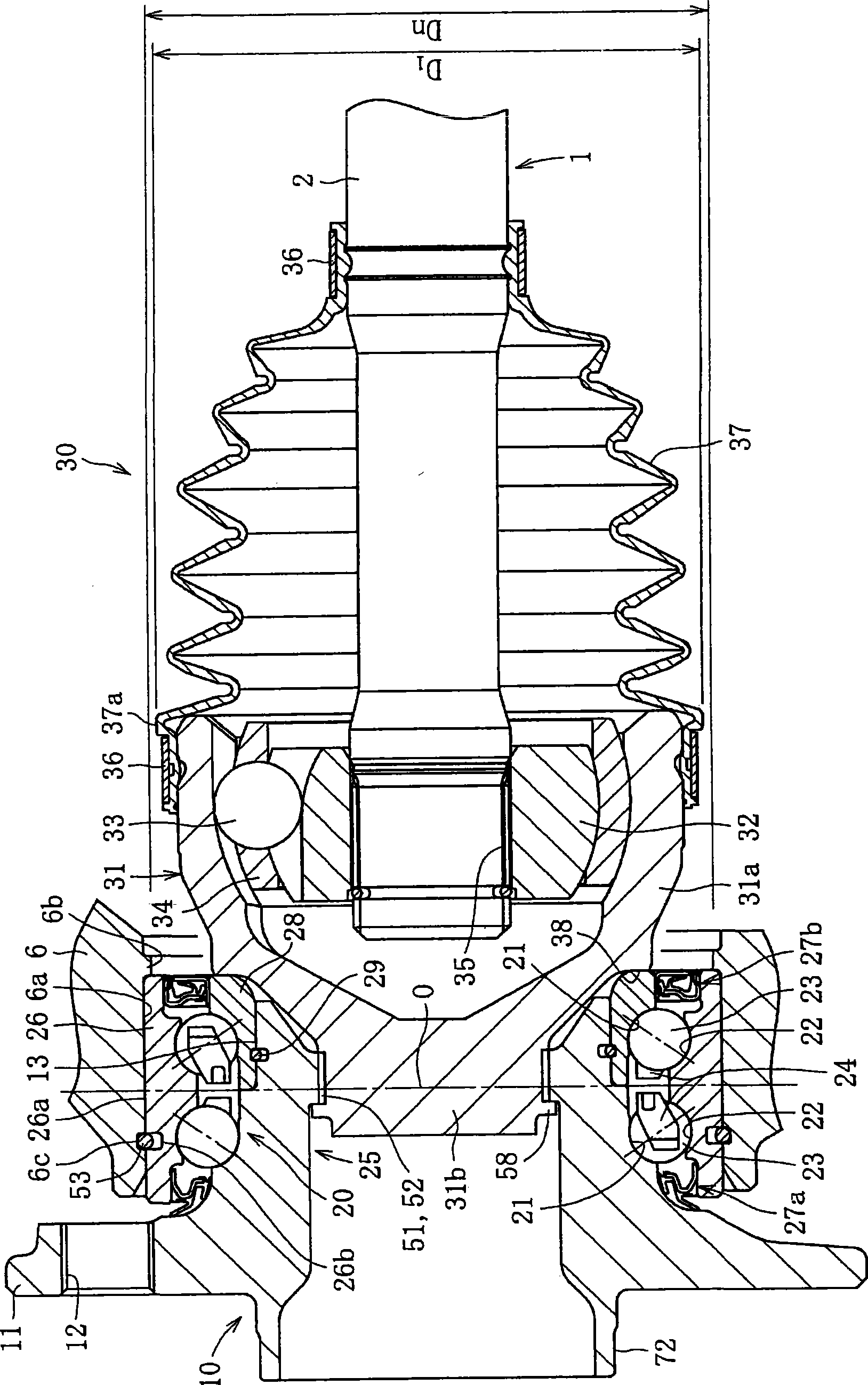
[0150] Next, embodiments of the bearing unit for driving wheels of the present invention will be described in detail.

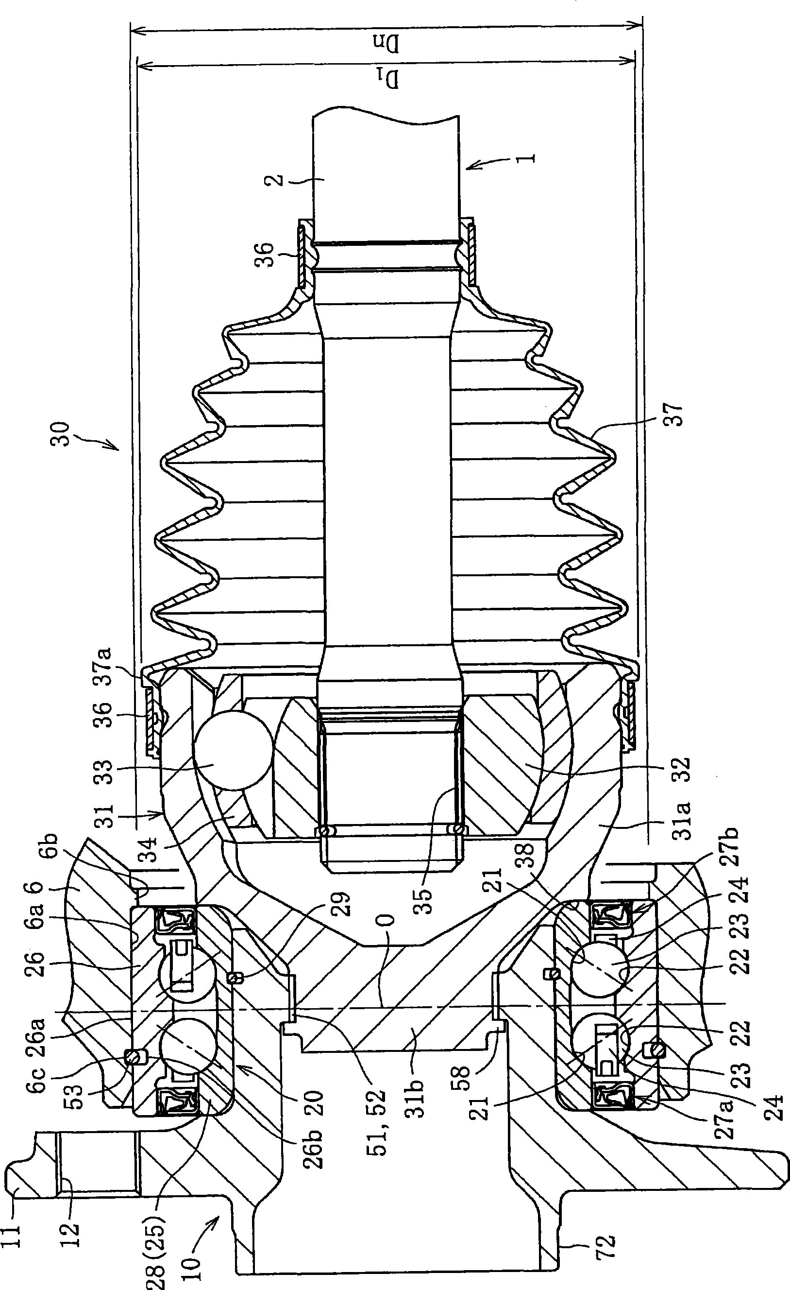
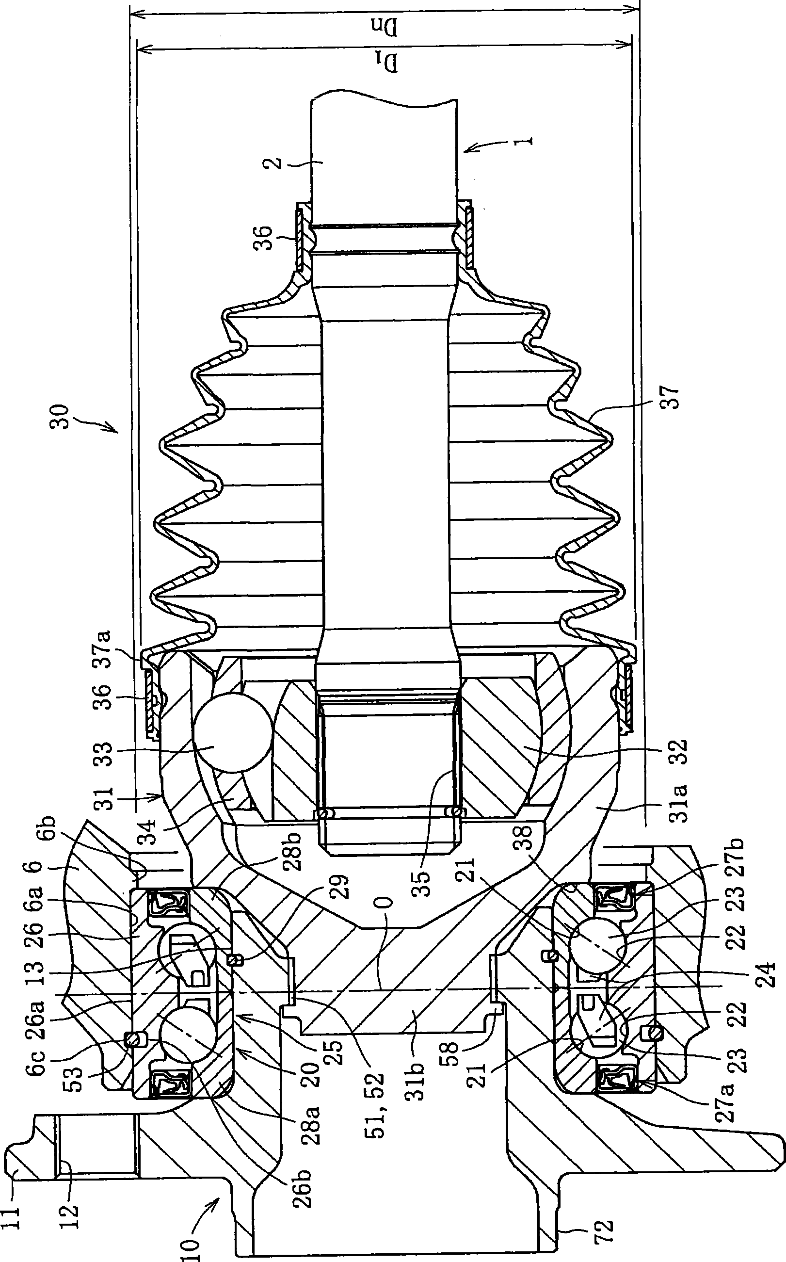
[0151] figure 1 The shown bearing unit for driving a wheel is composed of a hub 10 , a bearing portion 20 , and an outer constant velocity universal joint 30 .

[0152] The hub 10 includes a wheel attachment flange 11 for attaching a wheel (not shown) to its outer peripheral surface. A plurality of internal threads 12 are formed along the circumferential direction of the wheel mounting flange 11 , and wheel bolts (not shown) for fixing the wheel and disc are screwed into the internal threads 12 . The inner ring 28 is press-fitted into the small-diameter stepped portion 13 formed on the outer peripheral surface of the hub 10 with an appropriate amount of interference. A stop ring 29 is interposed between the inner peripheral surface of the inner ring 28 and the outer peripheral surface of the small-diameter stepped portion 13 , and the axial positioning of ...


PUM


Abstract

A process of assembling a driving wheel bearing unit, including a hub ring, a bearing, and a constant velocity universal joint, to a knuckle member is simplified. To achieve this, the hub ring (10) and an outer joint member (31) of an outboard side constant velocity universal joint (30) are plastically joined together. The outer periphery (26a) of an outer member (26) is press fitted into the inner periphery of the knuckle member, and the maximum diameter (D1) of the outboard side constant velocity universal joint (30) is set smaller than the minimum diameter (Dn) of the knuckle member (6). Also, the maximum diameter (D2) of an inboard side constant velocity universal joint (40) is set smaller than the minimum diameter (Dn) of the knuckle member (6).

Description

technical field [0001] The present invention relates to a bearing unit and drive shaft assembly for drive wheels of automobiles (front wheels of FF vehicles, rear wheels of FR vehicles, all wheels of 4WD vehicles). Background technique [0002] like Figure 45 As shown, the drive shaft 1 that transmits the power from the engine to the driving wheels has the following structure: the outer (vehicle body side side in the vehicle width direction) fixed constant velocity universal joint J1 is connected by the intermediate shaft 2, and the inner (on the vehicle body center side in the vehicle width direction) sliding constant velocity universal joint J2. The outer constant velocity universal joint J1 is connected to the hub 4 rotatably supported by the wheel bearing 3 , and the inner constant velocity universal joint J2 is connected to the drive shaft 5 . [0003] The wheel bearing 3 has a bearing inner ring 3a fixed to the outer periphery of the wheel hub 4, a bearing outer ring...

Claims


Application Information

Patent Timeline
IPC IPC(8): B60B35/14B60B35/18F16C19/18F16C25/08F16C33/60F16C35/063F16C35/067
Inventor 福村善一黑田正幸藏久昭友上真河村浩志福岛茂明
Owner NTN CORP
Learn More