

Speed reduction device
A technology of reduction gear and reduction mechanism, which is applied in the direction of transmission, gear transmission, bearing, etc., can solve problems such as easy damage, and achieve the effect of restraining damage and reducing inertia moment.
- Summary
- Abstract
- Description
- Claims
- Application Information
AI Technical Summary
Problems solved by technology
Method used
Image

Examples
Embodiment approach 1
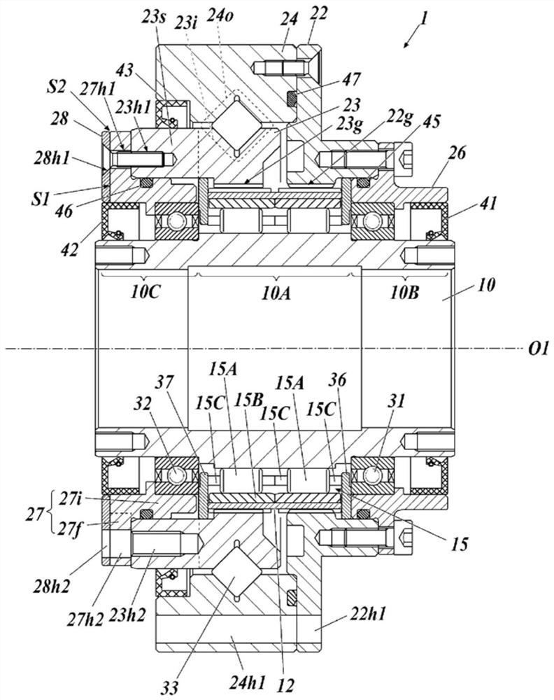
[0033] figure 1 It is a sectional view showing the reduction gear transmission according to Embodiment 1 of the present invention. In this specification, a direction along the rotation axis O1 is defined as an axial direction, a direction perpendicular to the rotation axis O1 is defined as a radial direction, and a rotation direction around the rotation axis O1 is defined as a circumferential direction.
[0034] The speed reduction device 1 according to the present invention is a flexural meshing gear device in which the external gear 12 is flexurally deformed to transmit rotational motion. Such as figure 1 As shown, the reduction gear 1 includes: a vibrating body shaft 10, an external gear 12 flexibly deformed by the vibrating body shaft 10, a first internal gear 22g and a second internal gear 23g meshing with the external gear 12, and a vibrating body bearing 15. Furthermore, the reduction gear transmission 1 includes: a first housing 22, a second member 23 having a secon...
Embodiment approach 2
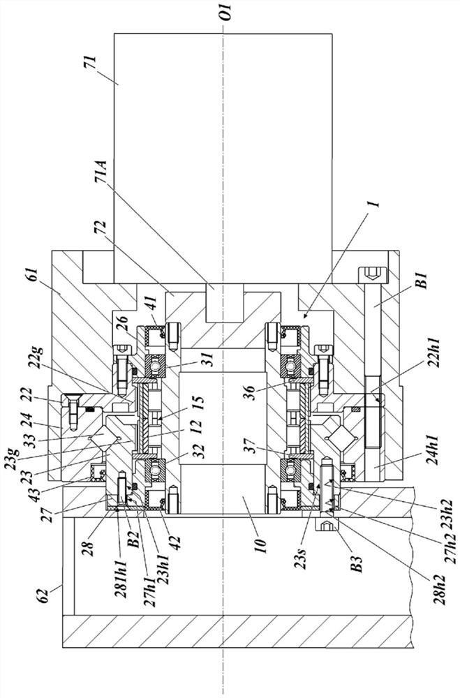
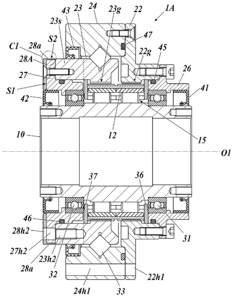
[0077] Figure 3A It is a sectional view showing the reduction gear transmission according to Embodiment 2 of the present invention. Figure 3B yes means Figure 3A A partially enlarged view of a part of . Figure 4 Yes means assembled with Figure 3A A diagram of the drive system of the reduction gear.
[0078] The difference between the reduction gear transmission 1A and the drive system of the second embodiment and the first embodiment mainly lies in the form of the protective member 28A, and the other parts are the same as those of the first embodiment. Therefore, the same reference numerals as those in Embodiment 1 are assigned to the same constituent elements, and detailed description thereof will be omitted.
[0079] In Embodiment 2, the second cover 27 and the load-side end of the second member 23 are snap-fitted into the concave portion 62g of the driven member 62 (refer to Figure 4 ). The second cover 27 has an axially facing surface S1 facing the driven membe...
Embodiment approach 3
[0084] Figure 5 It is a sectional view showing the reduction gear transmission according to Embodiment 3 of the present invention.
[0085] In the reduction gear transmission 1B according to Embodiment 3, the second protruding portion 28b that engages with (opposes in the axial direction) a part of the oil seal 42 adjacent to the second cover 27 is provided on the inner peripheral portion of the protective member 28B. Other than that, it is substantially the same as Embodiment 1. The second protruding portion 28b may also be provided on the protection member 28A of the second embodiment. exist Figure 5 In , the driven member 62 is shown by phantom lines.
[0086] As described above, according to the reduction gear transmission 1B according to Embodiment 3, the protection member 28B can function as a detachment preventing member for the oil seal 42 based on the second protruding portion 28 b.
PUM
 Abstract
Description
Claims
Application Information