
Connecting structure of multiple eccentric shafts and synchronous driving device thereof

A technology of synchronous drive and connection structure, applied in the directions of roads, road repair, roads, etc., can solve the problems of low reliability, unapplied end face teeth or end face teeth meshing, short service life, etc., to achieve the effect of simple structure

Inactive Publication Date: 2014-08-20
TENGHU MECHANICAL TECH CHIZHOU
View PDF7 Cites 3 Cited by
  • Summary
  • Abstract
  • Description
  • Claims
  • Application Information

AI Technical Summary

Problems solved by technology

[0002] Among the existing vibratory rollers, the exciter of the circular vibratory roller is one or two or more than two eccentric shafts arranged in series and then driven by a vibrating motor installed on the same axis to rotate synchronously and in the same direction. The eccentric shafts are usually connected by spline pairs; Patent No. 2005100658746 (CN1673457A) discloses a new type of synchronous reverse drive device with multiple eccentric shafts connected in series for the vibrating wheel of a directional vibratory roller. The first rotating shaft I, the second transmission shaft II, and the third transmission shaft III in the reverse drive device are all spline shafts or spline sleeves, and the connection structure between the synchronous reverse drive device and the multiple eccentric shafts driven by it It is also connected by spline pairs, teeth or teeth and other meshing pairs. This is actually a simple rigid coupling. In practical applications, due to the "nutation" of multiple eccentric shafts, coupled with the vibration motor or synchronous drive The coaxiality error between the multiple eccentric shafts makes this structure must use a spline pair with a large gap during manufacture, so the service life of this structure is short and the reliability is low. In addition, due to the vibration theory in use Creep elongation such that face teeth or face teeth engagement cannot be applied

Method used


Image

  • Connecting structure of multiple eccentric shafts and synchronous driving device thereof
  • Connecting structure of multiple eccentric shafts and synchronous driving device thereof
  • Connecting structure of multiple eccentric shafts and synchronous driving device thereof

Examples


Embodiment Construction

[0017] This application uses a vibrating wheel with three eccentric shafts connected in series and its double gear row synchronous reverse drive device as a typical example to illustrate.

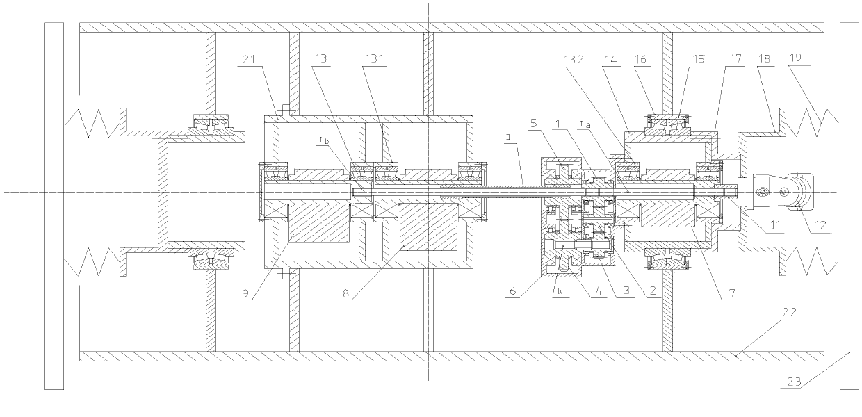
[0018] figure 1 The working process of a vibrating wheel using three eccentric shafts connected in series and its synchronous reverse drive device shown is: the vibrating motor 12 drives the first output shaft gear shaft right half shaft I through the coupling sleeve 11 a Rotation, first output shaft pinion right half shaft I a Simultaneously drive the right eccentric shaft 7, the forward output gear shaft 1, and the forward output gear shaft 1 simultaneously drives the first output shaft gear shaft left half shaft I b , The first output shaft gear shaft left half shaft I b Then drive the left eccentric shaft 9 to rotate synchronously with the right eccentric shaft 7; the forward output gear shaft 1 also drives the axle gear 2, the first synchronous gear 3, the second synchronous gear 4, ...


PUM


Abstract

The invention discloses a connecting structure of multiple eccentric shafts and a synchronous driving device thereof. The connecting structure mainly comprises a synchronous reverse output gear shaft, a second output shaft gear sleeve and a middle eccentric shaft, wherein the synchronous reverse output gear shaft is arranged in a gear box of the synchronous driving device; the middle eccentric shaft is arranged in a left exciter shell; straight tooth splines are arranged in inner holes of the synchronous reverse output gear shaft and the middle eccentric shaft; the left end meshed segment and the right end meshed segment of the second output shaft gear sleeve are provided with drum-shaped teeth; the normal tooth profiles of the drum-shaped teeth are the same as those of the straight tooth splines in the inner holes of the synchronous reverse output gear shaft and the middle eccentric shaft; the synchronous reverse output gear shaft and the middle eccentric shaft are connected with each other through a drum-shaped tooth meshing pair.

Description

technical field [0001] The invention relates to a connection structure between multiple eccentric shafts and their synchronous driving devices, in particular to a connection structure between multiple eccentric shafts and their synchronous driving devices of an exciter of a vibratory road roller, and belongs to the field of road construction machinery. Background technique [0002] Among the existing vibratory rollers, the exciter of the circular vibratory roller is one or two or more than two eccentric shafts arranged in series and then driven by a vibrating motor installed on the same axis to rotate synchronously and in the same direction. The eccentric shafts are usually connected by spline pairs; Patent No. 2005100658746 (CN1673457A) discloses a new type of synchronous reverse drive device with multiple eccentric shafts connected in series for the vibrating wheel of a directional vibratory roller. The first rotating shaft I, the second transmission shaft II, and the ...

Claims


Application Information

Patent Timeline
Patent Type & Authority Applications(China)
IPC IPC(8): E01C19/28
Inventor 陈启方张晨
Owner TENGHU MECHANICAL TECH CHIZHOU
Learn More