Method for calibrating a sensor cluster in a motor vehicle

A technology for motor vehicles and sensors, which is applied in the direction of vehicle components, instruments, electromagnetic wave re-radiation, etc., and can solve the problems of sensor assembly calibration that is not suitable for multiple sensors, insufficient sensors, etc.

Active Publication Date: 2014-08-20
VOLVO CAR CORP
View PDF8 Cites 12 Cited by
  • Summary
  • Abstract
  • Description
  • Claims
  • Application Information

AI Technical Summary

Problems solved by technology

[0009] While the calibration device suggested by US 2009033926 may provide an adequate calibration of imaging sensors for some situations, the device of US 2009033926 is not suitable for calibration of sensor assemblies comprisin...

Method used


Image

  • Method for calibrating a sensor cluster in a motor vehicle
  • Method for calibrating a sensor cluster in a motor vehicle

Examples


Embodiment Construction

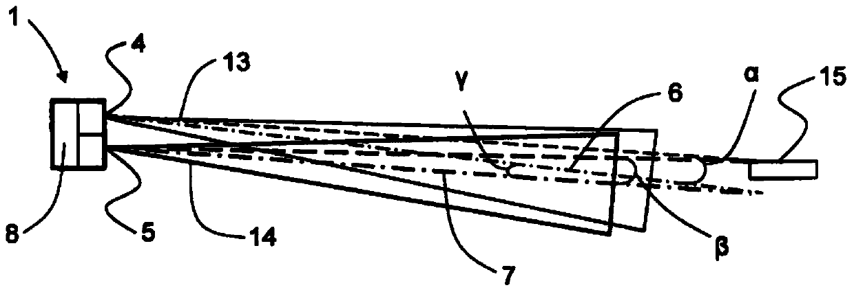
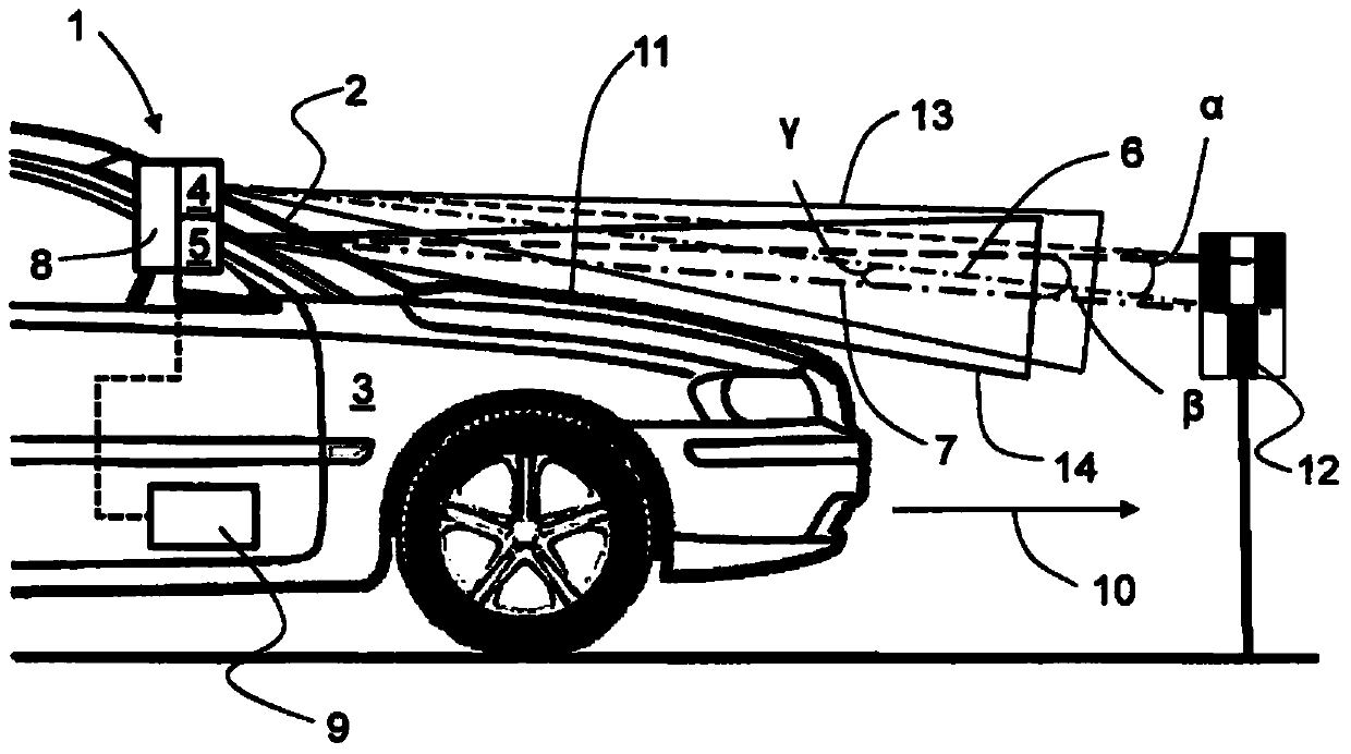
[0027] In general, embodiments herein relate to a method for calibrating a sensor assembly 1 located at a motor vehicle 3 , comprising at least a narrow beam sensor 4 and an imaging sensor 5 mounted in the same housing. The sensors 4 , 5 of such a sensor assembly 1 are calibrated relative to each other during the manufacture of the sensor assembly 1 so that the respective sensors 4 , 5 are correctly aligned with each other. Since the sensors 4 , 5 are usually arranged side by side either horizontally or vertically, said alignment generally means that there will be an angle between the directions 6 , 7 of the two sensors 4 , 5 . In the following, this angle between the orientations of the two sensors 4, 5 will be referred to as angle γ.

[0028] The narrow beam sensor 4 can be a radio detection and ranging (RADAR) technology sensor or a light detection and ranging (LIDAR) technology sensor or other sensor based on the use of stimulated emission of radiation for light wave ampli...


PUM


Abstract

Embodiments herein relate to a method for calibrating a sensor cluster (1) which is located at an inside of a windshield (2) of a motor vehicle (3) and arranged such that the pitch thereof is adjustable. The sensor cluster (1) at least comprises a narrow beam sensor (4) and an imaging sensor (5) both of which are directed forward of the motor vehicle (3). An angle gamma (y) between the center directions (6, 7) of the narrow beam sensor (4) and the imaging sensor (5) of the sensor cluster (1) has been pre-calibrated and stored in at least one memory unit (8, 9). The method comprises the steps of: calibrating at least one of the narrow beam sensor (4) and the imaging sensor (5) of the sensor cluster (1) with respect to a geometrical travel axis (10) of the motor vehicle (3); recording a measure epsilon (µ) corresponding to an angle between a center direction (7) of the imaging sensor (5) and a reference provided by a fixed vehicle (3) structural part (11); and storing the recorded measure epsilon (µ) in the at least one memory unit (8, 9).

Description

technical field [0001] Embodiments herein relate to a method for calibrating a sensor cluster positioned inside a windscreen of a motor vehicle, the sensor cluster comprising at least a narrow beam sensor and an imaging sensor. [0002] Further embodiments herein also relate to a motor vehicle comprising a sensor assembly comprising at least a narrow beam sensor and an imaging sensor, and the sensor assembly has been calibrated according to the method described above. Background technique [0003] In motor vehicles, sensor assemblies are used to record the vehicle environment. In particular, sensor assemblies are used in driver assistance systems. [0004] In order to provide data for such driver assistance systems, the use of sensor assemblies in motor vehicles is becoming more and more common, sometimes comprising sensors of different technologies, the extent of which may at least partially overlap. In particular, the use of sensor assemblies consisting of two different ...

Claims


Application Information

Patent Timeline
IPC IPC(8): G06T7/00B60R11/04G01S13/931G01S17/931
CPCG01S13/867G01S17/936G01S2007/4034G01B11/26G01S7/4972G01S13/931G01S17/931G01S7/4034
Inventor M·索伊尼宁M·文兰克
Owner VOLVO CAR CORP
Why Eureka
Try Eureka