
System and method for deteching roll rate sensor fault

Inactive Publication Date: 2005-09-06
FORD GLOBAL TECH LLC
View PDF233 Cites 12 Cited by
  • Summary
  • Abstract
  • Description
  • Claims
  • Application Information

AI Technical Summary

Benefits of technology

[0010]The present invention utilizes steering wheel angle, yaw rate, lateral acceleration, and vehicle speed signals to verify roll rate signal. Following the detection

Problems solved by technology

Sensor fault is not always detectable by sensor self test and / or system electronic monitoring, having detection relying on the fault to violate sensor specification.

Method used


Image

  • System and method for deteching roll rate sensor fault
  • System and method for deteching roll rate sensor fault
  • System and method for deteching roll rate sensor fault

Examples


Embodiment Construction

[0017]In the following figures the same reference numerals will be used to identify the same components. The present invention is preferably used to detect roll rate sensor fault in conjunction with a dynamic control system for an automotive vehicle, such as a yaw control system or a rollover control system. However, the present invention may also be used to detect roll rate sensor fault in any vehicle system including a roll rate sensor.

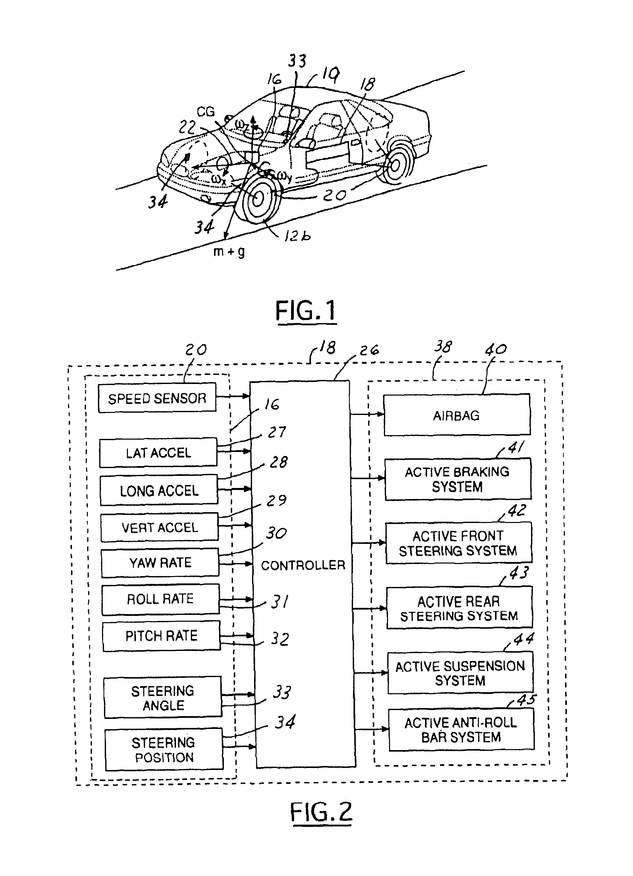
[0018]Referring to FIGS. 1 and 2, a safety system 18 for an automotive vehicle 19 having a sensing system 16 (sensing cluster), including a roll rate sensor 31, and a controller 26, is illustrated. Various forces and moments are acting thereon during a rollover condition.

[0019]The vehicle safety system 18 includes the sensor system 16. The sensing system 16 may use a six control sensor set including three axial accelerometers including a lateral accelerometer 27, a longitudinal accelerometer 28, and a vertical accelerometer 29 and three axial rotati...


PUM


Abstract

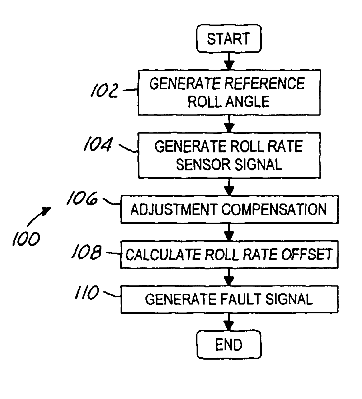
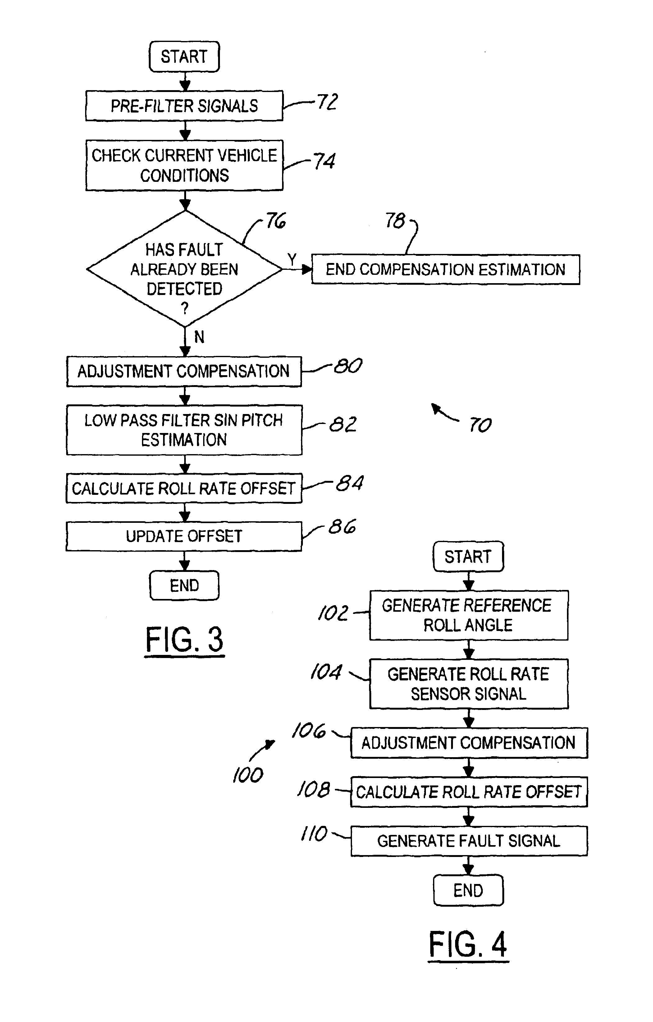
A control system for an automotive vehicle having a vehicle body includes a sensor cluster having a housing oriented within the vehicle body. A roll rate sensor is positioned within the housing and generates a roll rate sensor signal corresponding to a roll angular motion of the sensor housing. A controller receives the roll rate sensor signal and generates a reference roll angle. The controller also compares the reference roll angle to the roll rate sensor signal and generates a roll rate sensor fault signal in response a fault determined in said roll rate sensor.

Description

RELATED APPLICATION[0001]The present invention claims priority to provisional application No. 60 / 400,155 filed on Aug. 1, 2002, the disclosure of which is incorporated by reference herein.TECHNICAL FIELD[0002]The present invention relates generally to automotive vehicle sensors, and more specifically, to a method and apparatus for detecting a roll rate sensor fault.BACKGROUND[0003]Current, rollover stability control (RSC) schemes address vehicle roll and include a variety of sensors sensing vehicle dynamic conditions. RSC systems further include a controller controlling a distributed brake pressure for reducing a tire moment such that the net moment of the vehicle is counter to the vehicle roll direction.[0004]The RSC sensors include a speed sensor, a lateral acceleration sensor, a roll rate sensor, and a yaw rate sensor. The roll rate sensor is typically utilized to estimate the roll angle and to calculate the desired control pressure. Fault modes of the roll rate sensor, therefore...

Claims


Application Information

Patent Timeline
IPC IPC(8): B60G17/015B60G17/016B60G17/0195B60T8/88B60R21/01B60T8/1755B60T8/172B60T17/22B60T8/24B60T8/17B60T8/00B60T17/18B60R16/02B60R21/00B60G17/018B60G17/0185B60R16/023B60R21/0132B60W30/04
CPCB60G17/0162B60G17/0182B60G17/0185B60G17/0195B60R16/0233B60R21/01B60R21/013B60R21/0132B60T8/00B60T8/172B60T8/1755B60T8/241B60T8/243B60T8/885B60T17/22B60G2600/08B60G2600/1871B60G2800/0194B60G2800/215B60G2800/80B60G2800/922B60R2021/0018B60R2021/01122B60R2021/01327B60T2230/03B60T2240/06B60T2270/413B60W30/04
Inventor HROVAT, DAVORIN DAVIDTSENG, HONGTEI ERICXU, LI
Owner FORD GLOBAL TECH LLC
Learn More