
Dry etching device

A technology of dry etching and equipment, applied in the direction of circuits, discharge tubes, electrical components, etc., can solve the problems of increasing abnormal discharge phenomena, limiting process uniformity, and difficult to maintain shape, so as to reduce the probability of direct contact with the lower electrode , Reduce the effect of abnormal discharge phenomenon

Inactive Publication Date: 2014-08-20
BOE TECH GRP CO LTD +1
View PDF6 Cites 2 Cited by
  • Summary
  • Abstract
  • Description
  • Claims
  • Application Information

AI Technical Summary

Problems solved by technology

[0003] The dry etching equipment in the prior art includes an upper electrode and a lower electrode. The reaction gas is blown out through the shower head above the upper electrode, and the reaction gas is blown to the reaction chamber through the through hole of the upper electrode. The plasma field formed by the blown gas is actually It is difficult to distribute evenly on the surface, generally the plasma density at the four corners and edges is small, and the direction of ions diverges outward, so the etching rate is low and the shape is difficult to maintain. This structure limits the uniformity of the process.
[0004] The current lower electrode is a whole piece, which can only be applied to a fixed-size substrate. If it needs to be upgraded, the old equipment must be completely discarded to buy another generation of new equipment. In addition, when the substrate is slightly broken, the lower electrode will be exposed due to the broken area. , if the dry etching is continued, the plasma will directly contact the lower electrode, which will increase the occurrence of abnormal discharge

Method used


Image

  • Dry etching device
  • Dry etching device
  • Dry etching device

Examples


Embodiment Construction

[0040] The following will clearly and completely describe the technical solutions in the embodiments of the present invention with reference to the accompanying drawings in the embodiments of the present invention. Obviously, the described embodiments are only some, not all, embodiments of the present invention. Based on the embodiments of the present invention, all other embodiments obtained by persons of ordinary skill in the art without making creative efforts belong to the protection scope of the present invention.

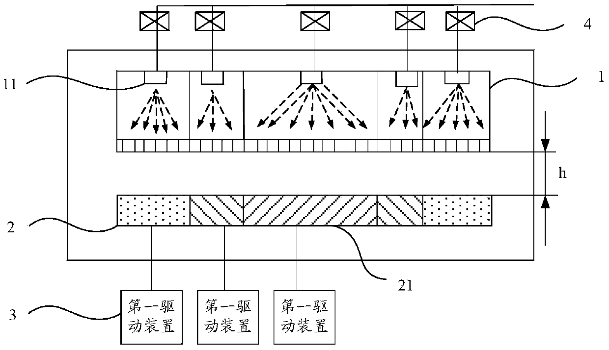
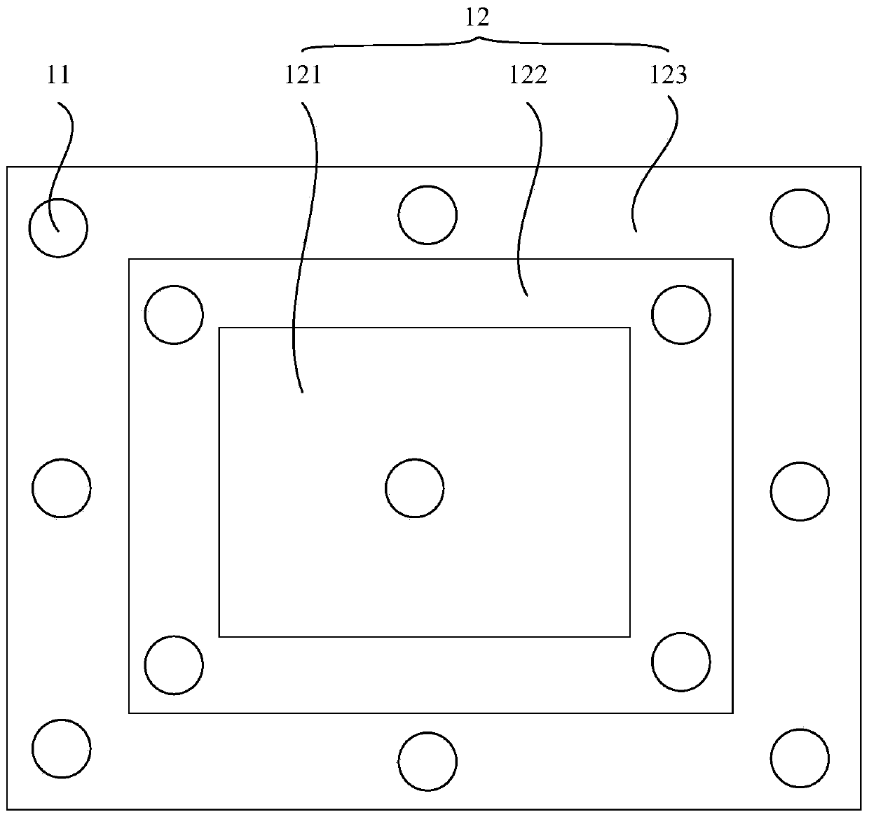
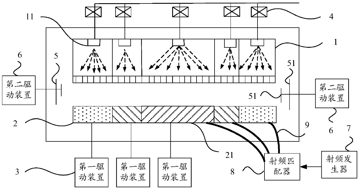
[0041] like figure 1 as shown, figure 1 A schematic structural diagram of a dry etching device provided in an embodiment of the present invention. The dry etching device provided in the present invention includes: an upper electrode 1 and a lower electrode 2 arranged oppositely, and the upper electrode 1 includes a plurality of nozzles distributed at intervals. The shower head 11 and the lower electrode 2 include a plurality of sub-lower electrodes 21 of diff...


PUM


Abstract

The invention discloses a dry etching device. The dry etching device can be applicable to fixing and etching substrates of different sizes, lowering the probability that plasma makes direct contact with a lower electrode and lowering the frequency of abnormal discharge. The dry etching device comprises an upper electrode and the lower electrode which are arranged oppositely, the upper electrode comprises a plurality of sprayers which are distributed at intervals, the lower electrode comprises a plurality of sub lower electrodes which are different in sizes, and the sub lower portions are arranged in a concentric mode and are nested sequentially from small to large. The dry etching device further comprises first drive devices, wherein each first drive device drives one sub lower electrode to move so as to adjust the distance between the sub lower electrode driven by the first drive device and the upper electrode, and the first drive devices are in transmission connection with the sub lower electrodes.

Description

technical field [0001] The invention relates to the technical field of display preparation, in particular to a dry etching device. Background technique [0002] Dry etching is a technique that uses plasma to etch thin films. When the gas exists in the form of plasma, it has two characteristics: on the one hand, the chemical activity of these gases in the plasma is much stronger than that under normal conditions. React with the material to achieve the purpose of etching and removal; on the other hand, the electric field can also be used to guide and accelerate the plasma, so that it has a certain energy. When it bombards the surface of the etched object, it will be etched The atoms of the object material are knocked out, so as to achieve the purpose of etching by physical energy transfer. Dry etching is the result of the balance between the physical and chemical processes on the wafer surface. [0003] The dry etching equipment in the prior art includes an upper electrode a...

Claims


Application Information

Patent Timeline
Patent Type & Authority Applications(China)
IPC IPC(8): H01J37/32
Inventor 张定涛刘聪郑云友宋泳珍李伟
Owner BOE TECH GRP CO LTD
Learn More