Photovoltaic direct current distribution cabinet and assembly method thereof
A DC power distribution cabinet and photovoltaic technology, applied in the cooling/ventilation of substation/switchgear, board/panel/desk, busbar/line layout of substation/switchgear, etc., can solve the limitations of DC power distribution cabinet installation and application, Different brand and specification requirements, high installation conditions and other issues, to achieve the effect of easy batch and assembly line operation production, good heat dissipation performance, safe and convenient operation and maintenance
Inactive Publication Date: 2014-08-20
CSR ZHUZHOU ELECTRIC LOCOMOTIVE RES INST
View PDF5 Cites 3 Cited by
- Summary
- Abstract
- Description
- Claims
- Application Information
AI Technical Summary
Problems solved by technology
In the existing DC power distribution cabinets, some of the whole cabinets are unreasonably arranged, resulting in complicated wiring inside the cabinet and inconvenient maintenance and repair.
[0005] 2. Different customers have different requirements for the number of confluence and distribution circuits of the DC power distribution cabinet, and some customers require the DC power distribution cabinet to have the insulation monitoring function of the DC system; different customers have requirements for the brand and specifications of the components in the DC power distribution cabinet Different, and different brands / specifications have different component sizes
Some of the existing DC power distribution cabinets are unreasonably designed, resulting in severe heat generation and even diode bursts when the DC power distribution cabinet is used on site.
[0007] 4. Some of the existing DC power distribution cabinets need to be maintained on the back of the cabinet, and a maintenance operation door needs to be opened on the back of the DC power distribution cabinet. The requirements for on-site installation conditions are relatively high, which limits the installation and application of DC power distribution cabinets
[0012] The above existing technologies need to be further improved in terms of heat dissipation performance, structure, expansion, manufacturing and installation.
Method used
View moreImage
Smart ImageViewing Examples

Examples
Embodiment 1
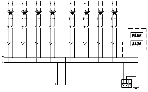
[0081] Embodiment 1: It is an 8-way converging DC power distribution cabinet, such as Figure 9 , Figure 11 shown.
Embodiment 2
[0082] Embodiment 2: It is a 10-way converging DC power distribution cabinet, such as Figure 10 , Figure 12 shown.
Login to View More PUM
 Abstract
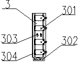
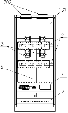
The invention discloses a photovoltaic direct current distribution cabinet and an assembly method thereof. The photovoltaic direct current distribution cabinet comprises a cabinet body, breaker assemblies, diode modules, an electrical panel assembly, a current sensor assembly and busbar assemblies, wherein the breaker assemblies, the diode modules, the electrical panel assembly and the current sensor assembly are installed on the front side of the middle inside the cabinet body, the rear side of the middle inside the cabinet body, the front side of the lower portion of the cabinet body and the front side of the lower portion of the cabinet body respectively, and the busbar assemblies are arranged in the middle of the cabinet body. The assembly method comprises the steps of installing a heat dissipation air channel system, installing the diode modules, installing the positive and negative busbar assemblies, installing the breaker assemblies, installing the electrical panel assembly and the current sensor assembly, and completing assembly. The whole photovoltaic direct current distribution cabinet is good in heat dissipation performance, simple in structure and easy to expand, manufacture and install. The cabinet body can be installed close to a wall, only the front end of the front surface of the cabinet body needs operation maintenance, use and maintenance are convenient, occupied space is reduced, the application range is expanded, and the construction and use cost is lowered for users.
Description
Technical field [0001] The invention involves the technology field of power distribution cabinets. Background technique [0002] The DC power distribution cabinet needs to achieve a flow distribution of the output of multiple flow boxes. Generally, the anti -anti -diode and DC switch of each input branch are required. The reasonable structure is very important.The existing DC power distribution cabinet, some of the entire cabinet structure is unreasonable, resulting in complex wiring in the cabinet and inconvenient maintenance and maintenance.Different customers have different requirements for the flow distribution circuit of the DC power distribution cabinet, and some customers require the DC power distribution cabinet to have the DC system insulation monitoring function; different customers have different demand for the brand and specifications of the components in the DC power distribution cabinet.There are differences in the size of different brands / specifications.DC power di...
Claims
Login to View More Application Information
Patent Timeline
 Patent Type & Authority Applications(China)
IPC IPC(8): H02B1/20H02B1/04H02B1/56
Inventor 蹇芳管仁德唐海燕唐洲陈艺峰刘玉柱姚明张蓉吴建雄廖远辉张洪浩
Owner CSR ZHUZHOU ELECTRIC LOCOMOTIVE RES INST
Features
- R&D
- Intellectual Property
- Life Sciences
- Materials
- Tech Scout
- Unparalleled Data Quality
- Higher Quality Content
- 60% Fewer Hallucinations
Learn More Browse by: Latest US Patents, China's latest patents, Technical Efficacy Thesaurus, Application Domain, Technology Topic, Popular Technical Reports.
© 2025 PatSnap. All rights reserved.Legal|Privacy policy|Modern Slavery Act Transparency Statement|Sitemap|About US| Contact US: help@patsnap.com