
Connecting process of far infrared nano electrothermal film electrode blind holes and wire

A far-infrared nano-wire connection technology, which is applied to ohmic resistance electrodes and ohmic resistance heating parts, can solve the problems of easy loosening and falling off of the connection between the wire and the electric heating film, so as to improve stability, increase service life and reduce looseness The effect of the probability of shedding

Inactive Publication Date: 2014-08-20
KMT纳米科技有限公司
View PDF5 Cites 7 Cited by
  • Summary
  • Abstract
  • Description
  • Claims
  • Application Information

AI Technical Summary

Problems solved by technology

[0003] The purpose of the present invention is to address the above technical problems, to provide a new process for connecting the blind hole of the far-infrared nanometer electrothermal film electrode and the wire, and to solve the problem that the connection between the wire and the electrothermal film is easy to loosen and fall off

Method used


Image

  • Connecting process of far infrared nano electrothermal film electrode blind holes and wire
  • Connecting process of far infrared nano electrothermal film electrode blind holes and wire

Examples


Embodiment 1

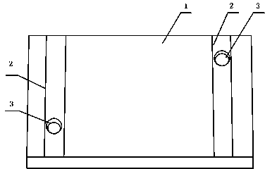
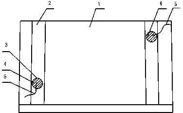
[0025] At both ends of the base material 1 with glass-ceramic as the far-infrared nano-electric heating film, use a φ6 hole opener to drill two blind holes 3 with a depth of 2mm, and use a 250-mesh screen on the position of the blind hole 3 of the base material 1. Print the electrode silver paste strips 2 at both ends, set the power to be below 1000w, and the width of the electrode silver paste strip 2 is 7mm, and then embed a φ0.93 silver wire 5 in the blind hole 3, and then use a temperature of 90°C to low temperature The substrate 1 and the electrode silver paste belt 2 are heated for 6 minutes. The heated substrate 1 is taken out, and the high-temperature silver paste 4 with a silver content of 75% is injected into the blind hole 3 . Then put it into a low-temperature oven at 90° C. for drying for 15 minutes. After taking it out, put it into a high-temperature oven at 600°C for the first sintering, and the sintering time is 6 minutes. After high-temperature sintering, wh...

Embodiment 2

[0027] At both ends of the substrate 1 with ceramics as the far-infrared nano-electric heating film, use a φ6 hole opener to drill two blind holes 3, the depth of which is 2mm, and use 300 mesh screen printing on the position of the blind holes 3 of the substrate 1. Electrode silver paste strips 2 at both ends, the set power is above 2000w, the width of the electrode silver paste strip 2 is 12mm, and φ0.93 silver wire 5 is embedded in the blind hole 3, and then heated at a low temperature of 120°C Substrate 1 and electrode silver paste belt 2, the heating time is 7 minutes. The heated substrate 1 is taken out, and the high-temperature silver paste 4 with a silver content of 75% is injected into the blind hole 3 . Then put it into a low-temperature oven at 120° C. for drying, and the drying time is 15 minutes. After taking it out, put it into a high-temperature oven at 620°C for the first sintering, and the sintering time is 6 minutes. After high-temperature sintering, when t...


PUM


Abstract

Provided is a connecting process of far infrared nano electrothermal film electrode blind holes and a wire. The connecting process is characterized in that two blind holes are formed in the two ends of a substrate, electrode silver paste bands at the two ends are silkscreened, the substrate and the electrode silver paste bands are heated firstly, then silver paste is injected into the blind holes, one end of the wire is placed in the blind holes, repeated drying and sintering and secondary silver paste injection are carried out at different temperatures, an electrode and the wire can be firmly connected under the condition of switch-on and high temperature, the process can improve the stability of far infrared nano electrothermal film products, the probability that the connecting wire is loosened and falls off at the high temperature is greatly reduced, and the service life of a far infrared nano electrothermal film is prolonged.

Description

technical field [0001] The invention relates to a process for connecting an electrothermal film electrode to a wire, in particular to a process for connecting a blind hole of a far-infrared nanometer electrothermal film electrode to a wire. Background technique [0002] The far-infrared nano-electric heating film works and generates heat after being energized through the electrode connection wire. Whether the connection between the wire and the electrode is firm is related to the service life of the far-infrared nano-electric heating film and the reliability of product quality. In the prior art, the connection between the electrodes of the electrothermal film and the wires is generally connected through a connection card. Chinese patent CN202009081U provides a special wiring connection card for the electrothermal film, which uses flanges instead of rivets. The manufacturing cost of the card, but the complexity of the connection card process and the low firmness of the connec...

Claims


Application Information

Patent Timeline
Patent Type & Authority Applications(China)
IPC IPC(8): H05B3/03
Inventor 张志昌
Owner KMT纳米科技有限公司
Learn More