Discharge mechanism of sheet metal shearing machine

A metal sheet and shearing machine technology, applied in metal processing equipment, feeding devices, manufacturing tools, etc., can solve problems such as a lot of mold costs, shearing molds can only be used for special molds, affecting production efficiency, etc., to reduce the relative The effect of friction, ensuring conveying speed and protecting surface quality

Inactive Publication Date: 2014-08-27
HANGZHOU HENGLI CUTTING EQUIP
View PDF7 Cites 5 Cited by
  • Summary
  • Abstract
  • Description
  • Claims
  • Application Information

AI Technical Summary

Problems solved by technology

[0002] The metal sheet shearing machines currently on the market usually use the feeding system to send the sheet into the shearing die, and then the shearing die sets the action in advance to process the sheet, and then the sheet is sent to the In the next process, the shearing dies of the metal sheet shearing machine with this structure can only be used for special dies, that is, a set of dies can only process sheets of one specification and shape. If it is necessary to process sheets of other specifications and shapes It is necessary to change the mould, which not only requires a large amount of moulds, but also affects the production efficiency in the production process. For this reason, the applicant of the present invention has invented a shearing machine with a swingable shearing die. Traditional shearing machines generally only produce For a plate of one shape, only the friction between the conveyor belt and the plate in the discharge system can meet the conveying requirements, but the swingable shearing machine can cut out plates of different shapes according to the needs, and the difference between plates of different shapes and the conveyor belt The required conveying friction is different, and the traditional discharge system can no longer meet the high-speed production requirements. Therefore, the improvement of the discharge system has become an urgent requirement.

Method used


Image

  • Discharge mechanism of sheet metal shearing machine

Examples


Embodiment Construction

[0009] The specific implementation manner of the present invention will be described in detail below in conjunction with the accompanying drawings.

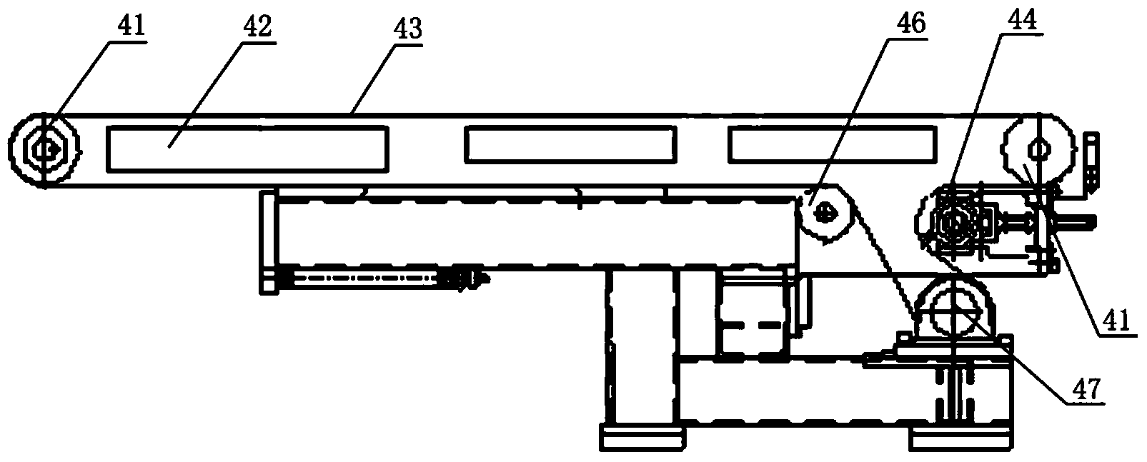
[0010] Such as figure 1 The discharge mechanism of a metal sheet shearing machine shown includes a discharge conveying device and a discharge supporting wheel mechanism, and the discharge conveying device includes a reduction motor 44, a conveying belt 43, an electromagnet 42 and two roller shafts 41, the two roller shafts 41, one is fixedly installed on the discharge side of the shearing die, and the other is fixedly installed at the entrance of the next station, and the conveying belt 43 is sleeved on the outside of the two roller shafts 41. The reduction motor 44 is connected with the roller shaft 41 and drives the roller shaft 41 to rotate. The electromagnet 42 is fixedly installed on the lower side of the conveyor belt 43, and the electromagnet 42 is connected with the control unit of the sheet metal shearing equipment. Bef...


PUM


Abstract

The invention relates to a discharge mechanism of a sheet metal shearing machine. The discharge mechanism comprises a slowdown motor, a conveying belt, an electromagnet and two roll shafts; one of the two roll shafts is fixedly mounted at the discharge side of a shearing die while the other one is fixedly mounted at the entrance of the next work position; the conveying belt is sleeved outside the two roll shafts; the slowdown motor is connected to the roll shaft and drives the roll shafts to rotate; the electromagnet used for increasing surface friction between a board material and the conveying belt is fixedly mounted at the lower side of the conveying belt. As the on-off time and the magnetic size of the electromagnet arranged in a discharged material conveying device are controlled, on one hand, the conveying speed is guaranteed, and on the other hand, the relative friction between the surface of the board material and the conveying belt is reduced to the maximum extent, and accordingly the surface quality is protected.

Description

technical field [0001] The invention relates to a metal sheet shearing machine, in particular to a discharge mechanism of the metal sheet shearing machine. Background technique [0002] The metal sheet shearing machines currently on the market usually use the feeding system to send the sheet into the shearing die, and then the shearing die sets the action in advance to process the sheet, and then the sheet is sent to the In the next process, the shearing dies of the metal sheet shearing machine with this structure can only be used for special dies, that is, a set of dies can only process sheets of one specification and shape. If it is necessary to process sheets of other specifications and shapes It is necessary to change the mould, which not only requires a large amount of moulds, but also affects the production efficiency in the production process. For this reason, the applicant of the present invention has invented a shearing machine with a swingable shearing die. Traditi...

Claims


Application Information

Patent Timeline
Patent Type & Authority Applications(China)
IPC IPC(8): B21D43/28
Inventor 张日祥裘利顺
Owner HANGZHOU HENGLI CUTTING EQUIP
Why Eureka
Try Eureka