Optical roller assembly with local optical effect patterns and local optical sheet manufacturing method

An optical effect, local technology, used in printing, rotary printing machines, printing devices, etc., can solve the problems of simultaneous pressing of vertical and horizontal gratings and optical patterns with various effects, uneven embossing, low efficiency, etc., to achieve the appearance Exquisite, low cost, cost reduction effect

Inactive Publication Date: 2014-08-27
EXTREME LENTICULAR PRINTING FACTORY
View PDF10 Cites 9 Cited by
  • Summary
  • Abstract
  • Description
  • Claims
  • Application Information

AI Technical Summary

Problems solved by technology

[0004] The present invention aims at the defects of low efficiency, high cost, uneven embossing, inability to simultaneously suppress vertical and horizontal grating patterns and various optical patterns with different effects on the same plane of the product in the existing optical embossing technology, and provides a One-time set of templates with a variety of different partial opti...

Method used


Image

  • Optical roller assembly with local optical effect patterns and local optical sheet manufacturing method
  • Optical roller assembly with local optical effect patterns and local optical sheet manufacturing method
  • Optical roller assembly with local optical effect patterns and local optical sheet manufacturing method

Examples


Embodiment 1

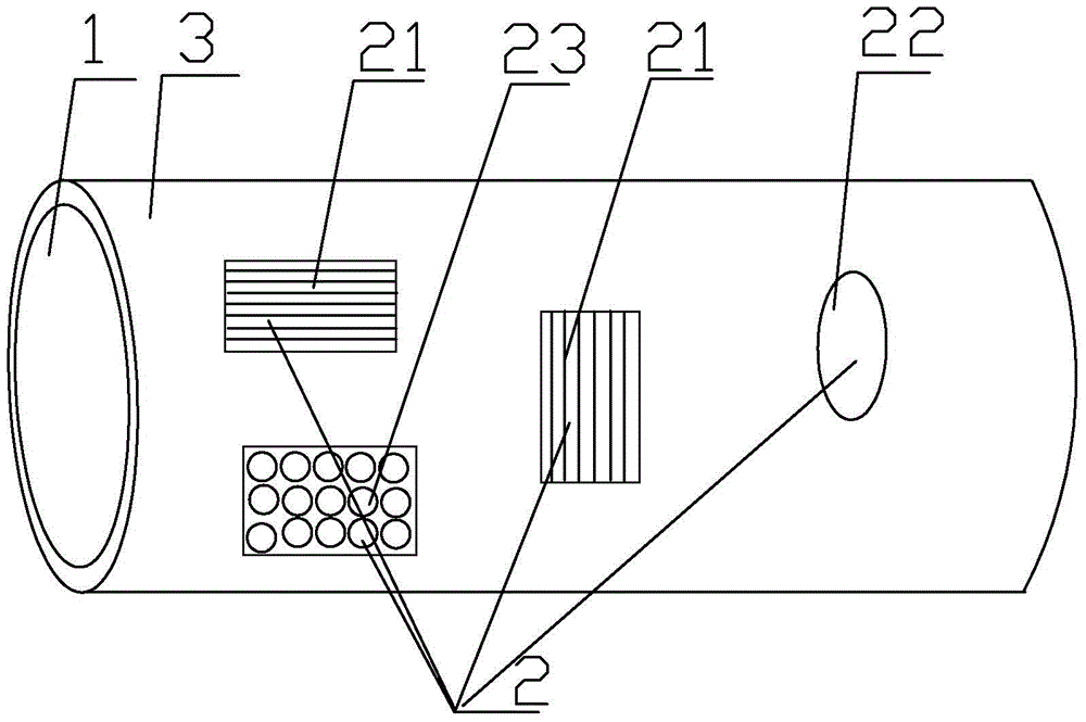
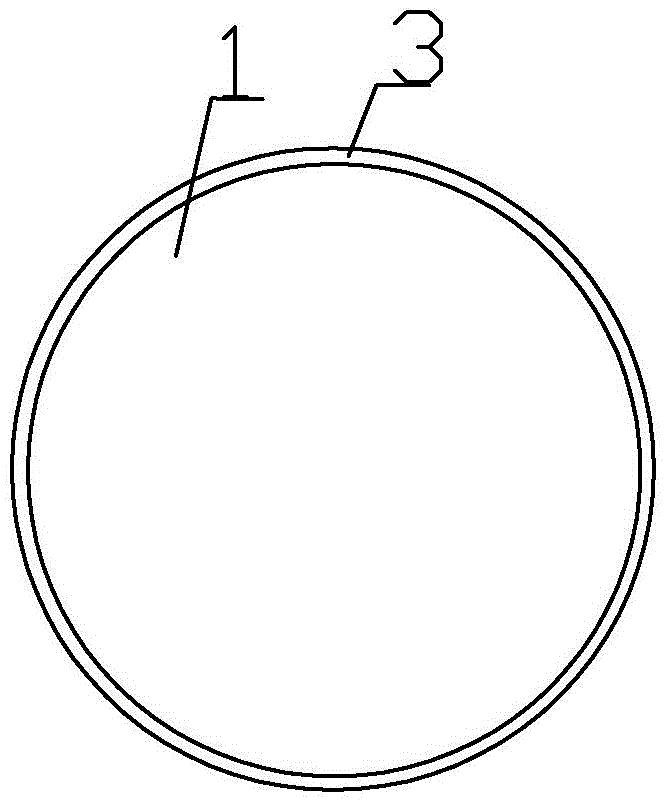
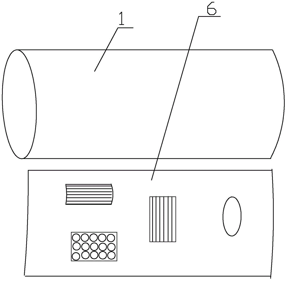
[0037] Please refer to figure 1 , figure 2 , image 3 As shown, the optical roller assembly of the partial optical effect pattern of the present invention includes a roller 1, the surface of the roller 1 is covered with a sleeve 3 with a partial optical effect pattern 2, and the sleeve 3 is formed by pressing the optical effect pattern 2 The metal plate 6 is made, preferably a nickel plate.

[0038] Please refer to Figure 4 As shown, the optical effect pattern 2 includes one or more of columnar or dot grating patterns 21 , micro-optical lens embossing patterns 22 and laser embossing patterns 23 . The grating pattern 21 includes a horizontal grating 211 and a vertical grating 212. The horizontal grating 211 and the vertical grating 212 can be distributed in the same part or in different parts. The first is that both are distributed in the same part, and the second is that both are distributed in different places, in Figure 4 Both of these can be clearly seen in . And ...

Embodiment 2

[0051] refer to Figure 5 , the difference from the embodiment is that the optical roller assembly of the partial optical effect pattern described in this embodiment includes a roller 1, and the surface of the roller 1 is covered with a template 4 with a partial optical effect pattern 2 in an adhesive manner , the template 4 is made of a nickel metal plate 6 capable of pressing the optical effect pattern 2 .

[0052] During manufacture, the two ends of the sheet metal 6 formed by the template 4 are covered and glued on the roller 1 to make it respectively. In the same way, when making plastic sheets, they are also coated and bonded to the rollers of the tablet press.


PUM


Abstract

The invention relates to the technical field of optical film production, and particularly discloses a optical roller assembly with local optical effect patterns and a method for manufacturing a local optical sheet and a three-dimensional printed pattern product. The optical roller assembly comprises a roller, and the surface of the roller is wrapped by or sleeved with a template or a sleeve with the local optical effect patterns. The local optical effect patterns include one or more of a column-shaped or dot grating pattern, a micro optical lens pressed pattern and a laser pressed pattern. Transverse gratings and longitudinal gratings in the column-shaped grating pattern are distributed in the same area or different areas. After the roller is bonded by means of the template or the sleeve with the optical effect patterns, the local optical effect patterns can be pressed on transparent sheets, and then patterns are positioned and printed on the local effect patterns to obtain exquisite products with high visuality. The optical roller assembly and the manufacturing method have the advantages that cost is low, efficiency is high and the method is easy and convenient to complement.

Description

technical field [0001] The invention relates to the technical field of optical film production, in particular to an optical roller assembly with a partial optical effect pattern, a method for making a partial optical effect pattern sheet by using the same, and a method for making a three-dimensional printing pattern product by local positioning. Background technique [0002] CN201220595612.6 discloses a novel partial grating roller, partial grating sheet and partial grating packaging box, and its purpose is to provide a partial grating roller, partial grating sheet and partial grating packaging box. The technical solution: the partial grating roller includes a grating part and a smooth surface part arranged at intervals, each grating of the grating part is in the shape of a convex lens, and the whole is a raised or concave groove, and the raised groove is the lowest The point is not lower than the surface point of the rolling surface part; the highest point of the concave gr...

Claims


Application Information

Patent Timeline
IPC IPC(8): B41F13/10B41C1/00B41C1/02B41M1/12B41M3/06B41M3/14
Inventor 何杰伟
Owner EXTREME LENTICULAR PRINTING FACTORY
Why Eureka
Try Eureka