Inflatable tire

A technology for pneumatic tires and tires, applied to the reinforcement layer of pneumatic tires, tire parts, tire edges, etc., can solve problems such as unexpectable effects, achieve the effect of preventing wear and improving durability

Inactive Publication Date: 2014-08-27
SUMITOMO RUBBER IND LTD
View PDF8 Cites 24 Cited by
  • Summary
  • Abstract
  • Description
  • Claims
  • Application Information

AI Technical Summary

Problems solved by technology

[0013] None of the techniques in the above-mentioned publications is aimed at preventing water from

Method used


Image

  • Inflatable tire
  • Inflatable tire
  • Inflatable tire

Examples


Embodiment 1

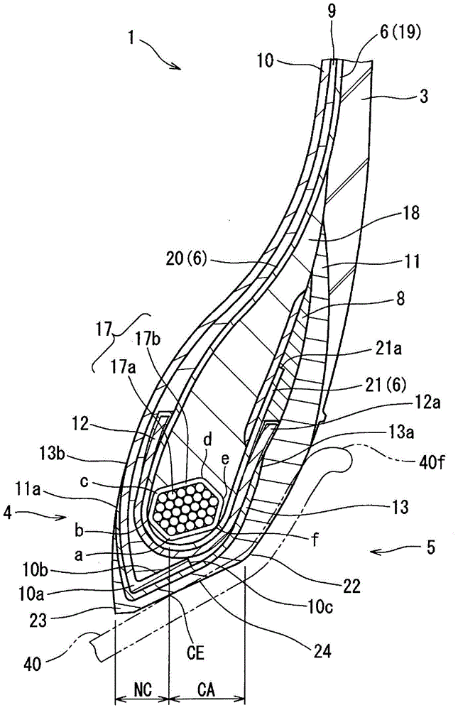
[0073] As Example 1, a figure 2 The shown heavy-duty pneumatic tire 1 has a U-shaped packing structure. The size of the tire 1 is 11R22.5. The rim on which this tire 1 is mounted is 7.50×22.5. This tire 1 has five ribs with a groove depth of 14.0 mm. As shown in Table 1, this tire 1 has a curved portion 10 b of an inner liner 10 with a rubber sheet 13 between the inner liner 10 and the chafer rubber 11 . The end portion 10c of the bent portion 10b is located axially outward from the radially innermost corner portion a of the bead core 17, that is, axially outward from the fitting end CE. Table 1 shows the thickness of the inner liner 10 and the composition ratio, physical properties and thickness of the rubber sheet. In order to evaluate the performance of the tire 1 of Example 1, the above-mentioned water-filled bench test and no-water bench test were carried out. Table 1 shows the test results (evaluation results) for this tire 1 .

Embodiment 2~10

[0075] As Examples 2-10, produced figure 2 The shown heavy-duty pneumatic tire 1 has a U-shaped packing structure. Various specifications of the inner liner 10 of the tire 1 and various specifications of the rubber sheet 13 are shown in Tables 1 and 2. Other configurations and test conditions of the above-mentioned tire 1 are the same as those of the above-mentioned Example 1. Table 1 and Table 2 show the test results (evaluation results) for the tire 1 described above.

Embodiment 11

[0077] As Example 11, produced Figure 4 The shown heavy-duty pneumatic tire 35 has a U-shaped packing structure. This tire 35 does not have the rubber sheet 13 . Various specifications of the inner liner 10 of the tire 35 are shown in Table 2. The other structures and test conditions of this tire 35 are the same as those of the above-mentioned Example 1. Table 2 shows the test results (evaluation results) for this tire 35 .


PUM

PropertyMeasurementUnit
Complex elastic modulusaaaaaaaaaa
Thicknessaaaaaaaaaa

Abstract

The invention provides an inflatable tire which can suppress water entering a tire bead core. The inflatable tire (1) comprises a tire bead part (4) provided with the annular tire bead core (17) along the circumference of the tire. The inflatable tire further comprises an inner lining (10), a tire bead wrapping rubber (11), a tire bead basal part (24) and a rubber sheet (13) clamped between the inner lining (10) and the tire bead wrapping rubber (11). In a tire (1) cross section including a central shaft plane, the end part (10c) of the inner lining (10) is located on a position closer to the tire axial outer side than the end part position (CE) of an embedding area (CP). The embedding area (CP) is in close connection with a tire rim (40) of the tire bead basal part (24). The thickness of the inner lining (10) at least on the embedding area is over 1.0mm.

Description

technical field [0001] The present invention relates to pneumatic tires. Background technique [0002] Figure 6 A bead portion 52 of a conventional heavy-duty pneumatic tire 51 is shown in . As shown in the figure, in the conventional tire 51 , the end portion 53 a of the inner liner 53 is usually positioned at (near) the bead toe portion 54 . The inner liner 53 has the effect of preventing air and moisture from penetrating. [0003] When the tire 51 is mounted on the rim and inflated, the bead toe 54 side of the bead base 55 is not in close contact with the surface of the rim 40 . A portion on the bead heel side that is in close contact with the surface of the rim 40 is referred to as a fitting area CA. The range that is not in close contact with the rim is called a non-fitting area NC. The boundary portion between the non-fitting region NC and the above-mentioned fitting region CA is referred to as "fitting end CE". [0004] For example, if the tire 51 is stored in t...

Claims


Application Information

Patent Timeline
IPC IPC(8): B60C5/14B60C9/02B60C15/04
Inventor 高田宣幸轰大辅
Owner SUMITOMO RUBBER IND LTD
Why Eureka
Try Eureka