Multiple-laser radar raster map merging system based on pilotless automobile

An unmanned vehicle and lidar technology, applied in the field of multi-lidar grid map fusion system, can solve the problems of high cost, practical limitations, complex structure, etc., to simplify the structure, improve the safety, and achieve a wide range of applications. Effect

Inactive Publication Date: 2014-08-27
BEIJING UNION UNIVERSITY
View PDF7 Cites 42 Cited by
  • Summary
  • Abstract
  • Description
  • Claims
  • Application Information

AI Technical Summary

Problems solved by technology

The navigation method of the driverless car also has the problems of complex structure, high cost and limited practicability

Method used


Image

  • Multiple-laser radar raster map merging system based on pilotless automobile
  • Multiple-laser radar raster map merging system based on pilotless automobile
  • Multiple-laser radar raster map merging system based on pilotless automobile

Examples


Embodiment 1

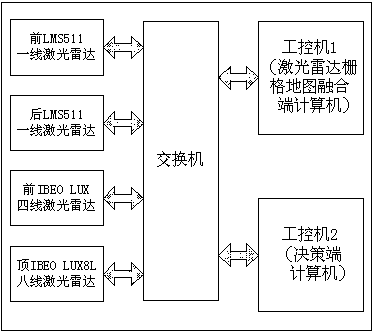
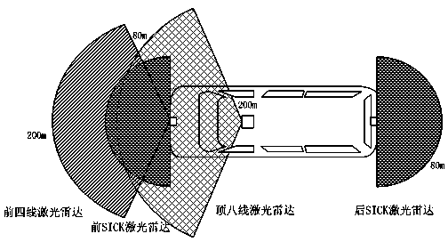
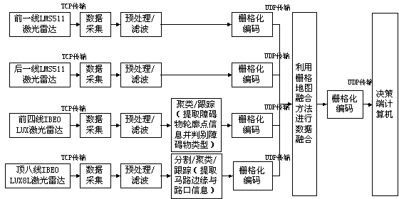
[0038] A multi-laser grid map fusion system based on driverless cars, including laser radars, switches and industrial computers; the laser radars include one-line laser radars and four-line laser radars installed in front of driverless cars, and The eight-line laser radar on the roof, and the one-line laser radar installed behind the car; the industrial computer includes a first industrial computer and a second industrial computer; the laser radar communicates with the first industrial computer through a switch and utilizes Ethernet Connect, the laser radar data is transmitted to the first industrial computer through the switch using Ethernet, and the first industrial computer analyzes and preprocesses the data, and then performs data processing for different laser radars, and performs rasterization on the effective data after processing. Grid code and transmit the coded value to the first industrial computer responsible for data fusion through Ethernet, then use the raster map...

Embodiment 2

[0040] A multi-lidar grid map fusion system based on unmanned vehicles is similar to Embodiment 1, the difference is that the first-line laser radar is 1 if there is an obstacle, and 0 if there is no obstacle; during the transmission process, Only transmit the coordinates of the grid image of 1; convert the data coordinates of each laser radar into the coordinates of the front-line laser radar; then, use the grid map fusion method to perform data fusion on the grid coded laser radar data .

Embodiment 3

[0042] A multi-lidar grid map fusion system based on unmanned vehicles is similar to Embodiment 2, the difference is that the grid map fusion method, as a fusion strategy, stipulates the priority of eight-line laser radar data The priority is the highest, followed by the four lines, and the priority of the first line is the lowest, and its coded values ​​are fused.


PUM


Abstract

The invention relates to a multiple-laser radar raster map merging system based on a pilotless automobile. The multiple-laser radar raster map merging system based on the pilotless automobile comprises a one-line laser radar and a four-line laser radar, the two of which are mounted in front of the pilotless automobile, an eight-line laser radar mounted at the roof of the automobile, and a one-line laser radar mounted at the tail of the automobile; the laser radars are connected with a first industrial personal computer by use of a switch and by virtue of Ethernet; the data of the laser radar are transmitted to the first industrial personal computer by use of the switch and by virtue of the Ethernet, and the first industrial personal computer is used for analyzing and preprocessing the data; data are processed for different laser radars, respectively, and rasterization coding is performed on valid data and the coded values are transmitted to the first industrial personal computer in charge of data fusion by virtue of the Ethernet; next, data fusion is carried out by use of a raster map merging method and the rasterization coding is performed on the data, and finally, the coded values are transmitted to a second industrial personal computer by virtue of the Ethernet. The multiple-laser radar raster map merging system is used for solving the problem that the pilotless automobile and an assistant-driving automobile collide with a barrier, and therefore, the safety of the automobile in the driving process is improved.

Description

technical field [0001] The invention belongs to the technical field of driverless cars, and relates to a multi-laser radar grid map fusion system, in particular to a multi-laser radar grid map fusion system based on driverless cars. Background technique [0002] Since the birth of intelligent robots, unmanned vehicles have attracted much attention as an active safety or assisted driving system to help people drive safely and reduce traffic accidents; as a difficult technical problem, it involves a variety of technologies and disciplines Crossover, among them, environmental perception technology has a very critical position. Driverless cars can rely on their own sensors to collect real-time road information around the vehicle and the state of the vehicle itself, and respond quickly based on the detected obstacle information, thereby preventing traffic accidents. However, at present, for driverless cars, a single sensor can no longer provide enough environmental information f...

Claims


Application Information

Patent Timeline
Patent Type & Authority Applications(China)
IPC IPC(8): B60R16/023B60R21/01G01S17/93G01S17/08G05D1/02
Inventor 高美娟朱学葵田景文张松松戈广双李尚年
Owner BEIJING UNION UNIVERSITY
Why Eureka
Try Eureka