
Built-in power telescopic dredging machine

A technology of power telescoping and dredging machines, applied in the field of dredging machines, which can solve problems such as short service life, harsh working environment, and high cost

Inactive Publication Date: 2014-08-27
武汉市经盛机电设备制造有限公司
View PDF7 Cites 0 Cited by
  • Summary
  • Abstract
  • Description
  • Claims
  • Application Information

AI Technical Summary

Problems solved by technology

Method one is labor-intensive, the working environment is harsh, low efficiency, high labor costs, and more seriously, personal safety accidents are likely to occur: the material suddenly collapses and the operator is buried alive; method two is likely to cause damage to the silo and uncontrollable dredging effect And it is not easy to operate, and there are obvious safety hazards at the same time; the third method not only has low dredging efficiency, and the dredging effect is not obvious, but also causes a large amount of dust to pollute the air and the outflow of sewage pollutes the water environment, and it also has great limitations and is easy to change. The physical and chemical properties of the materials make this method prohibitive for these materials; the fourth method is difficult to install, and the wall structure of the silo will inevitably be damaged, the installation period is long, the production line must be shut down during the installation process, the cost is high, and vibration is inevitable cause damage to the silo equipment; method five has achieved the dredging of the silo materials to a certain extent, but it also has great limitations: installation is difficult, the wall structure of the silo will inevitably be damaged, the installation period is long, and the installation During the process, the production line must be shut down; the cost is high, because the equipment is fixed on the warehouse wall, the dredging range of each set of equipment is limited, which requires a set of dredging equipment to be installed without a certain distance around the warehouse wall to meet the dredging requirements. The cost is high, and at the same time, the power device of the dredging equipment has been buried in the material, resulting in corrosion and denaturation of the equipment, resulting in a short service life, and the power device is easily "buried" by the material, causing the equipment to fail to move in the material. At the same time In a large-capacity silo, it is not easy to "move" the dredging device

Method used


Image

  • Built-in power telescopic dredging machine
  • Built-in power telescopic dredging machine
  • Built-in power telescopic dredging machine

Examples


Embodiment Construction

[0020] Embodiments of the present invention are described in detail below, examples of which are shown in the drawings, wherein the same or similar reference numerals designate the same or similar elements or elements having the same or similar functions throughout. The embodiments described below by referring to the figures are exemplary only for explaining the present invention and should not be construed as limiting the present invention.

[0021] In describing the present invention, it is to be understood that the terms "center", "upper", "lower", "front", "rear", "left", "right", "vertical", "horizontal", The orientations or positional relationships indicated by "top", "bottom", "inner", "outer", etc. are based on the orientations or positional relationships shown in the drawings, and are only for the convenience of describing the present invention and simplifying the description, rather than indicating or implying the It should not be construed as limiting the invention ...


PUM


Abstract

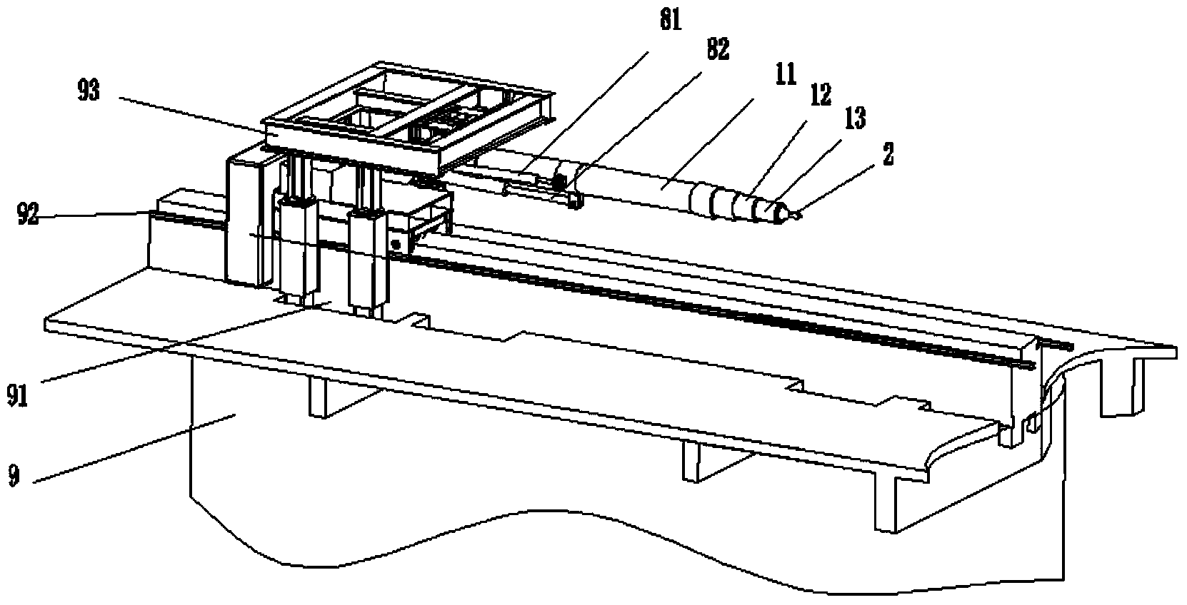
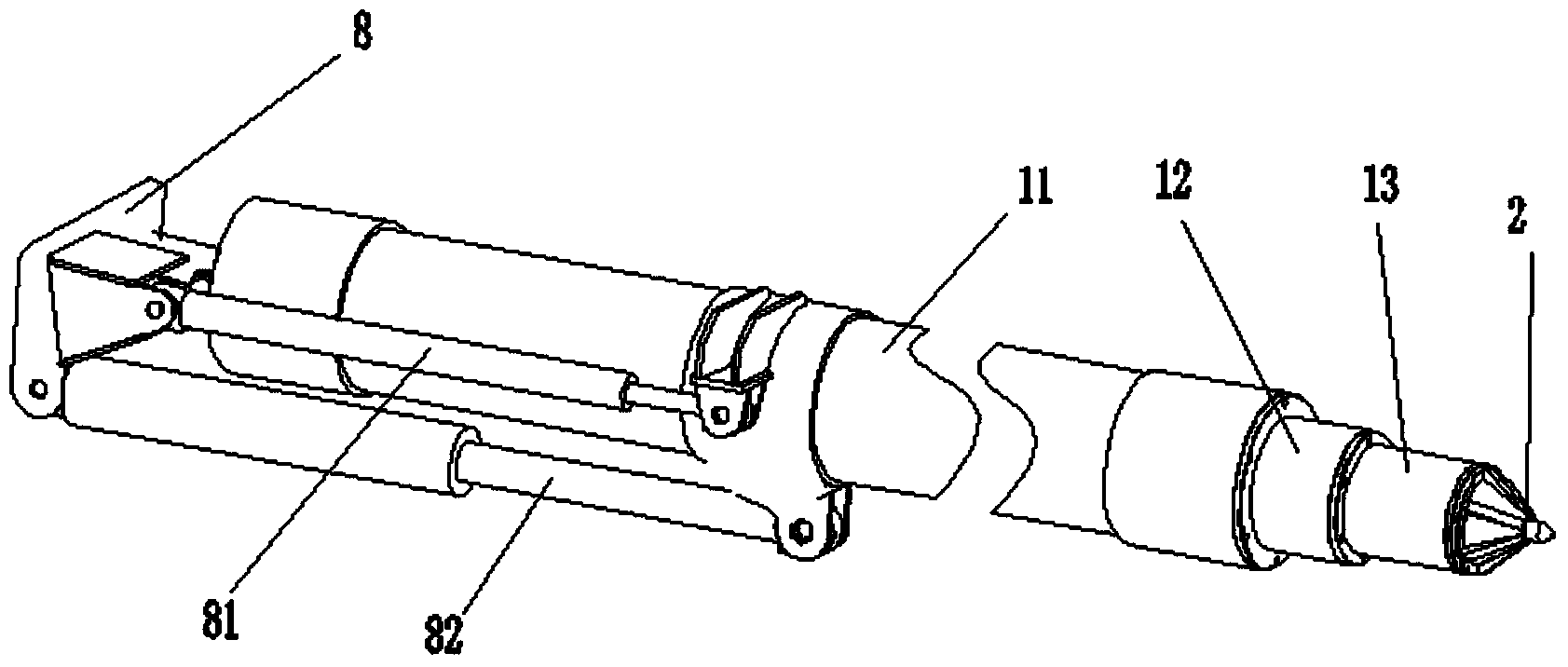
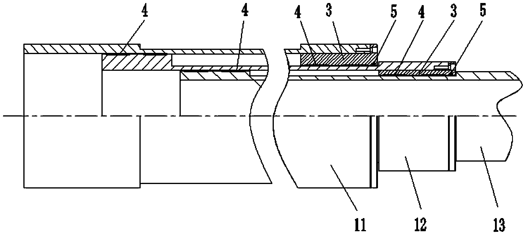
The invention discloses a built-in power telescopic dredging machine. The built-in power telescopic dredging machine comprises a stand, a power device, a telescopic rod connected with the power device and a dredging head 2, the telescopic rod is a hollow telescopic rod and at least comprises a first telescopic rod 11 and a last telescopic rod 13, the first telescopic rod 11 is connected with the stand, the power device is mounted in the telescopic rod for providing the stretching power for the telescopic rod, and the dredging head is mounted at the end of the last telescopic rod. The built-in power telescopic dredging machine uses the telescopic rod to dredge materials, the operation is agile; the power device is mounted in the telescopic rod, so that the power device is avoided from being embedded in the materials, the power device safety is guaranteed, and the service life of the dredging machine is prolonged.

Description

technical field [0001] The invention relates to a dredging machine, in particular to a telescopic dredging machine with built-in power for dredging material flow in a silo. Background technique [0002] At present, in iron and steel, electric power, coal, chemical industry, metallurgy, building materials and other industries, in order to save the land occupied by production materials, adjust the production process, allocate material selection paths, adjust the amount of material selection, balance the material selection process and the needs of automated production, Generally, the materials are accumulated and stored in the silo. The silo is generally cylindrical (or conical or square). Generally, a material conveyor belt feeding trolley is set to transport the material to the feed port of the silo, and the material is transported from the bottom of the silo. The discharge port is released, and then transported to the next production process through the conveyor belt. The m...

Claims


Application Information

Patent Timeline
IPC IPC(8): B65D88/66
Inventor 章忠祥蔡宇
Owner 武汉市经盛机电设备制造有限公司
Learn More