
Hydraulic starting system, method and crane

A hydraulic start and cold start technology, applied in the hydraulic field, can solve the problems of hydraulic system resistance torque increase, system compound action limitation, poor engine adaptability, etc., to achieve the effect of avoiding resistance torque and smooth start

Active Publication Date: 2017-04-12
XCMG CONSTR MACHINERY
View PDF10 Cites 0 Cited by
  • Summary
  • Abstract
  • Description
  • Claims
  • Application Information

AI Technical Summary

Problems solved by technology

[0003] At the ambient temperature where the hydraulic oil is suitable, the starting torque of the engine can overcome the instantaneous resistance torque caused by the displacement change of the variable pump at the moment of starting, and realize the smooth starting of the engine. , as the viscosity of the hydraulic oil increases, the resistance torque of the hydraulic system increases accordingly. When the resistance torque is greater than the starting torque of the engine itself, it is difficult for the engine to start normally
[0004] In order to solve this problem, the existing technology usually improves the engine by increasing the starting torque of the engine to improve the cold start performance in low temperature environment, but because the resistance torque that the engine needs to overcome is difficult to quantify, the adaptation of the improved engine Poor sex
On the other hand, the existing hydraulic system requires the main valve to be able to realize the unloading of the neutral function, but this requirement limits the possible realization of the main valve, and the neutral unloading of the main valve will cause serious damage to the compound action of the system. limit

Method used


Image

  • Hydraulic starting system, method and crane
  • Hydraulic starting system, method and crane
  • Hydraulic starting system, method and crane

Examples


Embodiment Construction

[0028] The technical solutions of the present invention will be described in further detail below with reference to the accompanying drawings and embodiments.

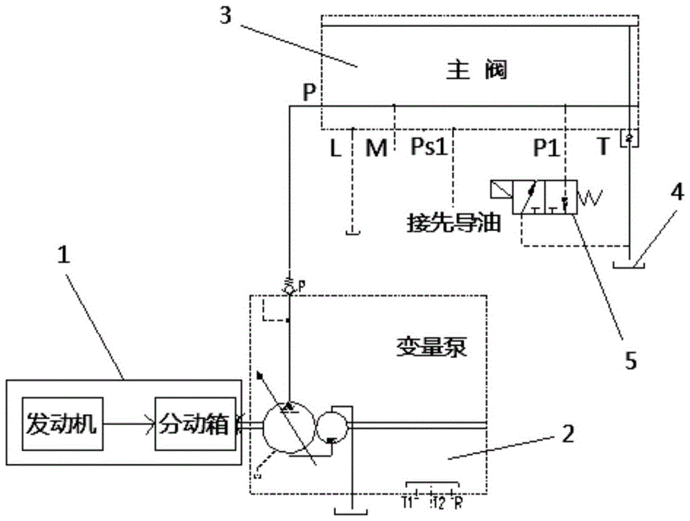
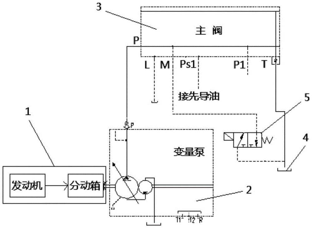
[0029] like figure 2 Shown is a schematic structural view of an embodiment of the hydraulic starting system of the present invention. In this embodiment, the hydraulic starting system includes: a power mechanism 1, a variable pump 2, a main valve 3 and a hydraulic oil tank 4. The power mechanism 1 provides driving power to the variable pump 2. connected through the oil circuit.

[0030] The main valve 3 is provided with a plurality of oil ports, among which the oil inlet P is connected with the oil supply circuit of the variable pump 2, and the main valve 3 also has a cold start oil drain port, between the cold start oil drain port and the hydraulic oil tank 4 There is a solenoid valve 5 that controls the discharge of the variable displacement pump 2 during cold start. During cold start, the system can use the elec...


PUM


Abstract

The invention relates to a hydraulic starting system, a method and a crane. The hydraulic starting system comprises a power mechanism, a variable pump, a main valve and a hydraulic oil tank, wherein the power mechanism is used for providing driving power to the variable pump; the variable pump and the hydraulic oil tank are both communicated with the main valve through oil paths; the main valve is provided with an oil inlet which is communicated with an oil supply path of the variable pump; the main valve is further provided with a cold start oil drainage port; a solenoid valve for controlling the drainage load of the variable pump in cold start is further arranged between the cold start oil drainage port and the hydraulic oil tank. As the solenoid valve is arranged between the cold start oil drainage port and the hydraulic oil tank, and the oil supply path inside the main valve and the hydraulic oil tank are communicated through the solenoid valve in cold start, the unloading operation of the variable pump is achieved. By adopting the structure, the variable pump can be firstly unloaded when the power mechanism is in cold start, the hydraulic system is prevented from relatively high resistance moment, and thus smooth starting of the power mechanism in a low temperature environment is achieved.

Description

technical field [0001] The invention relates to hydraulic technology, in particular to a hydraulic starting system, method and crane. Background technique [0002] For the crane hydraulic system using an open variable pump, the hydraulic oil displacement of the variable pump is at the maximum in the initial stage of starting, until the working pressure of the pump or the external pressure loaded on the pilot control port G of the variable pump is greater than a certain value (for example 30bar), the pump variable mechanism of the variable pump will adjust the hydraulic oil displacement of the variable pump to the minimum value under the action of hydraulic pressure. like figure 1 As shown, the variable pump is rotated by the engine of the crane through the transfer case. When the main valve connected to the variable pump cannot be unloaded in the neutral position, the hydraulic system will build up pressure at the moment the engine starts to realize the displacement of the ...

Claims


Application Information

Patent Timeline
Patent Type & Authority Patents(China)
IPC IPC(8): B66C13/20F15B11/00F15B13/02
Inventor 刘振华柏见涛王惠
Owner XCMG CONSTR MACHINERY
Learn More