Portable Probe Calibration System

A portable, bottom-fixed technology, applied in the field of drilling, which can solve the problems of inconvenient detection of probe pipes

Active Publication Date: 2017-01-11
BEIJING HAILAN SCI & TECH DEV
View PDF9 Cites 0 Cited by
  • Summary
  • Abstract
  • Description
  • Claims
  • Application Information

AI Technical Summary

Problems solved by technology

[0005] The invention provides a portable probe verification system to solve the problem of inconvenient probe verification where the detection location is often changed in the field and the working place is far away from the verification room.

Method used


Image

  • Portable Probe Calibration System
  • Portable Probe Calibration System
  • Portable Probe Calibration System

Examples


Embodiment Construction

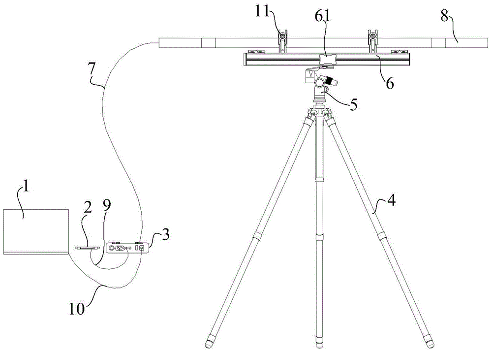
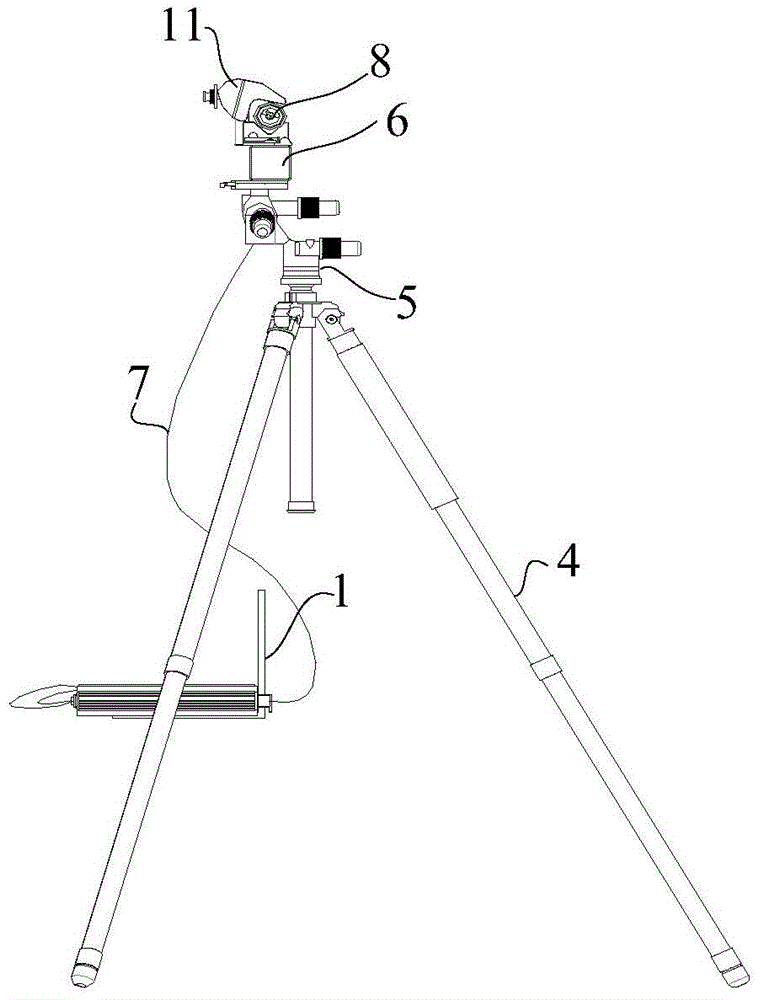
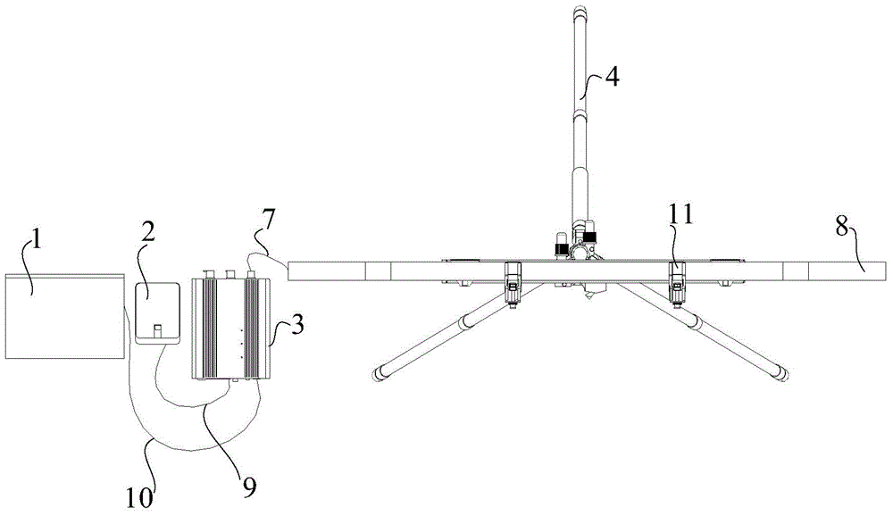
[0038] The embodiment of the present invention provides a portable probe tube verification system, which solves the problem of inconvenient probe tube verification when the detection location is often changed in the field and the working place is far away from the verification room.

[0039] In order to enable those skilled in the art to better understand the technical solutions in the embodiments of the present invention, and to make the above-mentioned purposes, features and advantages of the embodiments of the present invention more obvious and understandable, the technical solutions in the embodiments of the present invention are described below in conjunction with the accompanying drawings The program is described in further detail.

[0040] Please refer to the attached Figure 1-3 , Figure 1-3 The structure of the portable probe calibration system provided by the embodiment of the present invention is shown. The portable probe calibration system provided by the embodi...


PUM


Abstract

A portable exploring tube verification system comprises a support, a three-dimensional rotating shaft (5) arranged on the support, a clinometer (6) fixed on the three-dimensional rotating shaft (5), a clamp holder (11) arranged on the top surface of the clinometer (6) and used for fixing exploring tubes (8) on the clinometer (6) side by side, a data processing instrument (3) connected with the exploring tubes (8) through exploring tube data lines (7) and used for processing exploring tube detection data, a display connected with the data processing instrument (3) so as to display the detection data and a mobile power supply (2) connected with the data processing instrument (3), wherein the three-dimensional rotating shaft (5) can adjust the space angle of an adapter platform (55) on the three-dimensional rotating shaft (5); and the clinometer (6) is provided with a display screen (61) for displaying the inclination angles of the two ends of the clinometer relative to the horizontal plane. The verification system solves the problems that detections places are changed often outdoors and the verification on the exploring tubes at the working places far away from a verification chamber is inconvenient.

Description

technical field [0001] The invention relates to the technical field of drilling, and more specifically relates to a portable calibration system. Background technique [0002] During the drilling of coal and oil, the probe rod of the drilling equipment is drilled from the surface to the center of the earth. With the gradual deepening of the drilling end of the probe rod, the detection instrument set at the drilling end of the probe rod will successively transmit the detection data to the data analyzer set at the non-drilling end to realize data processing. [0003] A probe tube is arranged at the head end of the probe rod, and accelerometers for detecting azimuth coordinates in three directions of space are respectively arranged in the probe tube. The above three accelerometers can determine the specific drilling position of the probe rod, and then guide the probe rod to drill toward the detected coal source or oil source. After the probe rod works for a period of time, the...

Claims


Application Information

Patent Timeline
Patent Type & Authority Patents(China)
IPC IPC(8): E21B47/01E21B47/12
Inventor 杨彪
Owner BEIJING HAILAN SCI & TECH DEV
Why Eureka
Try Eureka