Novel optical fiber connector

An optical fiber connector and a new type of technology, which are applied in the coupling of optical waveguides and other directions, can solve the problems of unreasonable structural setting of optical fiber connectors, large processing difficulties and errors, and difficult to master the processing accuracy. , The effect of high assembly efficiency

Active Publication Date: 2014-08-27
宁波宇达光电股份有限公司
View PDF6 Cites 7 Cited by
  • Summary
  • Abstract
  • Description
  • Claims
  • Application Information

AI Technical Summary

Problems solved by technology

[0003] However, due to the unreasonable structural arrangement of the above-mentioned optical fiber connectors, there are the following defects in actual use: First, since four positioning protrusions 51' are evenly arranged on the outer wall of the metal tail handle 5', and are placed in the sleeve seat 2' The positioning groove corresponding to the positioning protrusion 51' is set, and the structural setting is relatively complicated. In addition, in order to avoid the rotation of the metal tail handle 5' along the tangential direction of the outer wall, the positioning protrusion 51' needs to be in close contact with the inner wall of the positioning groove during connection, and the processing accuracy Difficult to grasp, resulting in greater processing difficulty and errors; second, when the metal tail handle 5' is inserted into the sleeve seat 2', it is first necessary to align the positions of the positioning protrusions 51' and the positioning grooves. Due to the number of positioning protrusions 51' more, resulting in more inconvenient positioning and more cumbersome installation; third, since the rubber sleeve 9' is usually injection molded from plastic materials, the internal thread on the inner wall of the rubber sleeve 9' leads to higher manufacturing costs, and the use of threaded connections Assembly method, low assembly efficiency

Method used


Image

  • Novel optical fiber connector
  • Novel optical fiber connector
  • Novel optical fiber connector

Examples


Embodiment Construction

[0017] The present invention will be further described below in conjunction with the accompanying drawings.

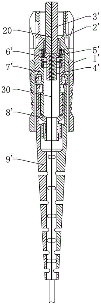
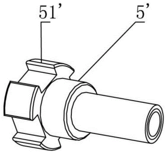
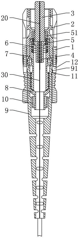
[0018] Such as Figure 3 to Figure 5 The new optical fiber connector shown includes a packaging shell 1, a socket seat 2, a first ferrule 3, a second ferrule 4, a metal tail handle 5, a spring 6, a support seat 7, a collar nut 8, and a rubber sleeve The tube 9, the sleeve socket 2 is sleeved in the packaging shell 1 and snap-fitted with the packaging shell 1, and the ends of the first ferrule 3 and the second ferrule 4 are inserted in the metal A ferrule assembly is formed in the tail handle 5, and the metal tail handle 5 is inserted in the sleeve seat 2. The support seat 7 is sleeved in the packaging shell 1 and its front end is engaged with the sleeve seat 2. The metal tail handle 5 The spring 6 is connected to the supporting seat 7, and the function of the spring 6 is to enable the ferrule assembly formed by the cooperation of the first ferrule 3, the second ferrul...


PUM


Abstract

The invention discloses a novel optical fiber connector comprising an outer packaging shell, a sleeve head base, a first insertion core, a second insertion core, a tail metal handle, a spring, a supporting base, a clamp screw cap and a rubber sleeve. The sleeve head base is sleeved with the outer packaging shell and matched with the outer packaging shell in a clamping mode. The end of the first insertion core and the end of the second insertion core are installed in the tail metal handle in an opposite insertion mode. The supporting base is sleeved with the outer packaging shell, the front end of the supporting base is matched with the sleeve head base in a clamping mode, and the tail end of the supporting base is sleeved with the clamp screw cap. A square groove is formed in the inner wall of the sleeve head base, a square block is arranged on the outer wall of the tail metal handle, a pair of clamping blocks is symmetrically arranged on the outer wall of the rubber sleeve, and buckles are arranged on the inner wall of the outer packaging shell and matched with the clamping blocks. Openings are formed in the walls of the outer packaging shell and communicated with the buckles. The novel optical fiber connector is simple and reasonable in structure, easy to machine, high in precision, convenient to install and position, low in manufacturing cost and high in assembly efficiency.

Description

technical field [0001] The invention relates to the technical field of optical fiber coupling devices, in particular to a novel optical fiber connector. Background technique [0002] With the continuous development of optical communication technology, optical fiber into copper and fiber to the home are widely used, and fiber optic connectors are also widely used in the connection of optical fibers. Optical fiber connectors can be divided into: FC, SC, ST, LC, D4, DIN, MU, MT, etc. according to the structure of the connector. Such as figure 1 and figure 2 As shown, the structure of SC fiber optic connectors currently on the market usually includes a package shell 1', a sleeve seat 2', a first ferrule 3', a second ferrule 4', a metal tail handle 5', and a spring 6 ', supporting seat 7', ring nut 8', and rubber sleeve 9', the sleeve seat 2' is sleeved in the packaging shell 1' and is snap-fitted with the packaging shell 1', the first The ends of a ferrule 3' and the second...

Claims


Application Information

Patent Timeline
Patent Type & Authority Applications(China)
IPC IPC(8): G02B6/38
Inventor 林军亮
Owner 宁波宇达光电股份有限公司
Why Eureka
Try Eureka