
Current source generator

A generator and current source technology, applied in the field of microelectronics, can solve the problems of low power consumption, high PSRR, low noise, etc.

Active Publication Date: 2014-08-27
SANECHIPS TECH CO LTD
View PDF7 Cites 10 Cited by
  • Summary
  • Abstract
  • Description
  • Claims
  • Application Information

AI Technical Summary

Problems solved by technology

[0011] The technical problem to be solved by the present invention is to provide a current source generator to solve the problem that current source generators in the prior art do not have low power consumption, high PSRR, and low noise at the same time, and to provide a A current source and a current source that increases with temperature (PTAT)

Method used


Image

  • Current source generator
  • Current source generator
  • Current source generator

Examples


Embodiment Construction

[0041] The present invention will be further described in detail below in conjunction with the accompanying drawings and embodiments. It should be understood that the specific embodiments described here are only used to explain the present invention, not to limit the present invention.

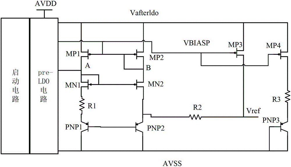
[0042] The invention provides a PRE-LDO structure (pre-low voltage drop regulator), adopting isolation and filtering methods to realize low power supply, low power consumption, accurate and adjustable current source generator.

[0043] For PSRR, it mainly adopts the cascode self-bias structure or the Pre-LDO pre-adjustment structure of the input voltage, and makes a compromise between low voltage and low power consumption;

[0044] For low noise, consider the selection of devices such as long-length MOS transistors, the use of isolation structures, and even some special considerations, such as the introduction of filter structures;

[0045] For the fine-tuned current generator, it is realized...


PUM


Abstract

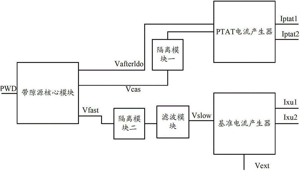
A current source generator comprises: a bandgap source core module (201) configured for generating a stable reference voltage; a separating module 1 (202), connected to the bandgap source core module (201) and configured for performing noise separation on the stable reference voltage; a filter (203), connected to the separating module 1 (202) and configured for filtering the stable reference voltage on which the noise separation has been performed; a reference current generator (204), connected to the filter (203) and configured for generating a reference current; a separating module 2 (205) connected to the bandgap source core module (201) and configured for performing noise separation on the stable reference voltage; and a PTAT current generator (206) connected to the separating module 2 (205) and configured for generating a current with a positive temperature coefficient.

Description

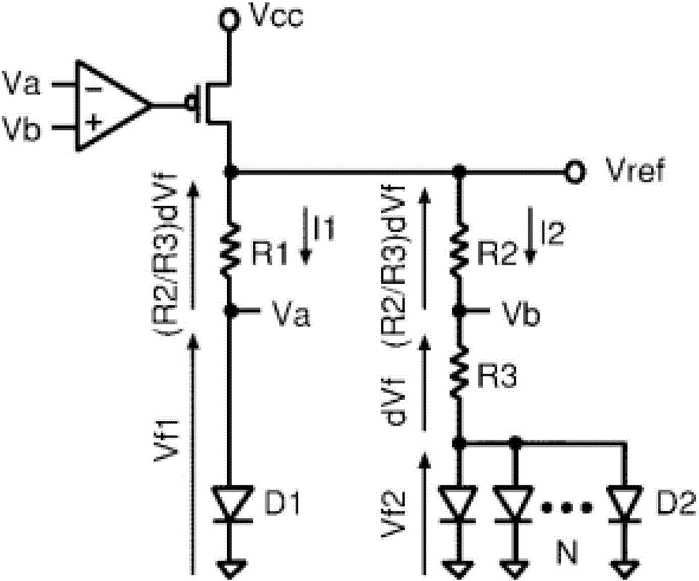
technical field [0001] The invention relates to the technical field of microelectronics, in particular to a current source generator with a reference source. Background technique [0002] In the field of electronic equipment, especially in the design of mobile radio frequency communication integrated circuits, it is necessary to use bandgap sources to generate low power consumption, high PSRR (Power Supply Rejection Ratio, power supply rejection ratio), low noise, ultra-low temperature coefficient, Adjustable and accurate voltage and current, but also need to generate accurate positive temperature coefficient current, such as low current as low as 1uA, 5uA. It is more important for a SOC (System on Chip, System on a Chip) chip, which requires low cost, and relies on digital adjustment, requires high PSRR, low output impedance, low power consumption, and small area, suitable for integration. [0003] like figure 1 It is a schematic diagram of the structure of the usual band...

Claims


Application Information

Patent Timeline
Patent Type & Authority Applications(China)
IPC IPC(8): G05F1/56
CPCG05F3/08G05F3/30
Inventor 易律凡谢豪律
Owner SANECHIPS TECH CO LTD
Learn More