Supercharge Your Innovation With Domain-Expert AI Agents!

Processor and control method for processor

A processor and control circuit technology, applied in the direction of program control design, electrical digital data processing, instruments, etc., can solve the problem of increased processing time and achieve the effect of shortening the processing time

Inactive Publication Date: 2014-08-27
SOCIONEXT INC
View PDF6 Cites 3 Cited by
  • Summary
  • Abstract
  • Description
  • Claims
  • Application Information

AI Technical Summary

Problems solved by technology

Delay in setting configuration information in each logic circuit may result in increased processing time

Method used


Image

  • Processor and control method for processor
  • Processor and control method for processor
  • Processor and control method for processor

Examples


Embodiment Construction

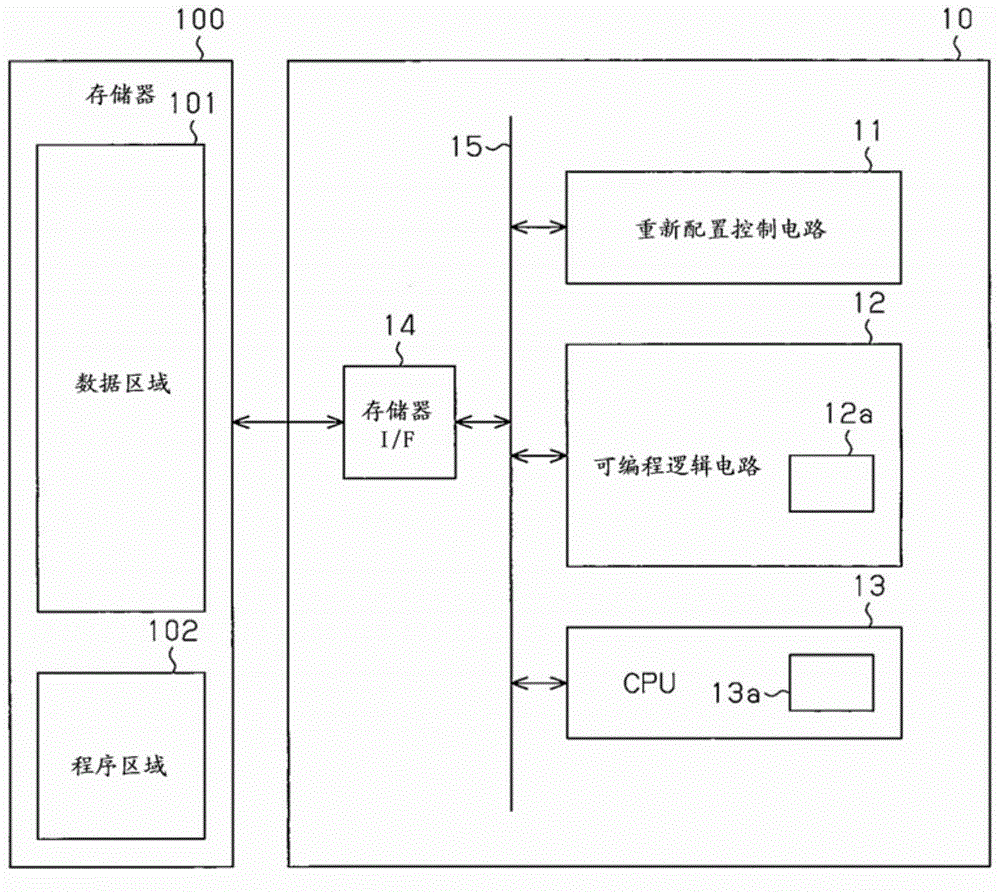
[0017] Referring to the accompanying drawings, an embodiment will now be described below. Such as figure 1 As shown in , the processor 10 includes a reconfiguration control circuit 11, a programmable logic circuit 12, a central processing unit (hereinafter referred to as CPU) 13 and a memory interface ( figure 1 memory I / F) 14, they are coupled through a bus 15 to communicate with each other.

[0018] The memory interface 14 is coupled to the memory 100 . The memory 100 is, for example, a dynamic random access memory (DRAM). Reconfiguration control circuit 11 , programmable logic circuit 12 and CPU 13 access memory 100 via bus 15 and memory interface 14 .

[0019] The CPU 13 includes a memory 13a. The memory 13a is a nonvolatile memory and stores program data executed by the CPU 13 . CPU 13 stores reconfiguration information corresponding to processing to be executed by programmable logic circuit 12 in memory 100 and programmable logic circuit 12 . CPU 13 is an example o...


PUM


Abstract

A processor includes a programmable logic circuit (12) provided with a plurality of processing units (E01-E24). The programmable logic circuit is capable of reconfiguring a first logic circuit corresponding to first circuit configuration information (CI1)according to a first process and a second logic circuit corresponding to second circuit configuration information (CI2) according to a second process. Each of the first and second logic circuits includes an information holding unit (RR1, RR2, RR3 or RR4). A first control circuit (13) stores the second circuit configuration information in the information holding unit of the first logic circuit and generates an execution control signal (EX1) for executing the first process. A second control circuit (11) obtains the second circuit configuration information from the information holding unit of the first logic circuit in response to completion of the first process and controls the programmable logic circuit so as to reconfigure the second logic circuit corresponding to the second circuit configuration information.

Description

technical field [0001] The present disclosure relates to a processor and a control method for the processor. Background technique [0002] Japanese Laid-Open Patent Publication No. 2001-68993 describes an example of a semiconductor device including a programmable logic circuit. The logic circuit includes a plurality of calculation units and couples the calculation units according to configuration information provided from a control circuit (for example, CPU) provided in the semiconductor device. When the logic structure corresponding to the configuration information is configured in the logic circuit, the logic circuit outputs a completion flag. The control circuit is responsive to the completion flag and instructs the logic circuit to perform the calculation. Then, the logic circuit performs processing based on the instruction and outputs a completion flag when the processing is completed. In response to the completion flag, the control circuit sets subsequent configurat...

Claims


Application Information

Patent Timeline
Patent Type & Authority Applications(China)
IPC IPC(8): G06F9/30G06F9/38
CPCG06F9/3885G06F15/7867
Inventor 冈田一彦
Owner SOCIONEXT INC
Features
  • R&D
  • Intellectual Property
  • Life Sciences
  • Materials
  • Tech Scout
  • Unparalleled Data Quality
  • Higher Quality Content
  • 60% Fewer Hallucinations
Learn More