
Display Panel and Gate Driver

A gate driver and gate drive technology, applied in static indicators, instruments, etc., can solve problems such as difficulty in applying narrow borders, gate driver dynamic power consumption and circuit layout area increase, etc., to achieve improved aperture ratio and wide use The effect of value and area reduction

Active Publication Date: 2016-10-19
AU OPTRONICS CORP
View PDF5 Cites 0 Cited by
  • Summary
  • Abstract
  • Description
  • Claims
  • Application Information

AI Technical Summary

Problems solved by technology

In this way, the dynamic power consumption of the gate driver and the layout area of ​​the circuit will increase, and it will be more difficult to apply to narrow border applications.

Method used


Image

  • Display Panel and Gate Driver
  • Display Panel and Gate Driver
  • Display Panel and Gate Driver

Examples


Embodiment Construction

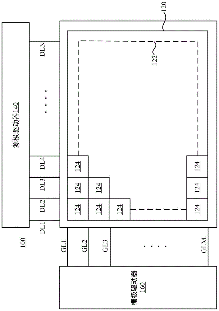
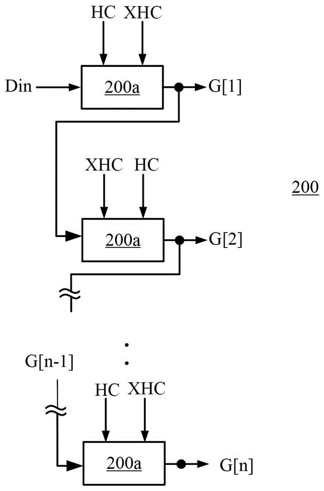
[0037] Specific embodiments of the present invention are given below, and the present invention is described in detail in conjunction with the drawings. However, the provided embodiments are not used to limit the scope of the present invention, and the description of the structure and operation is not used to limit the order of its execution. Any structure recombined by components to produce a device with equivalent functions is the present invention. scope covered by the invention. In addition, the drawings are for illustration purposes only and are not drawn to original scale. For ease of understanding, the same components will be described with the same symbols in the following description.

[0038] The terms "first", "second", ... etc. used herein do not specifically refer to a sequence or order, nor are they used to limit the present invention, but are only used to distinguish components or operations described with the same technical terms That's all.

[0039] As used...


PUM


Abstract

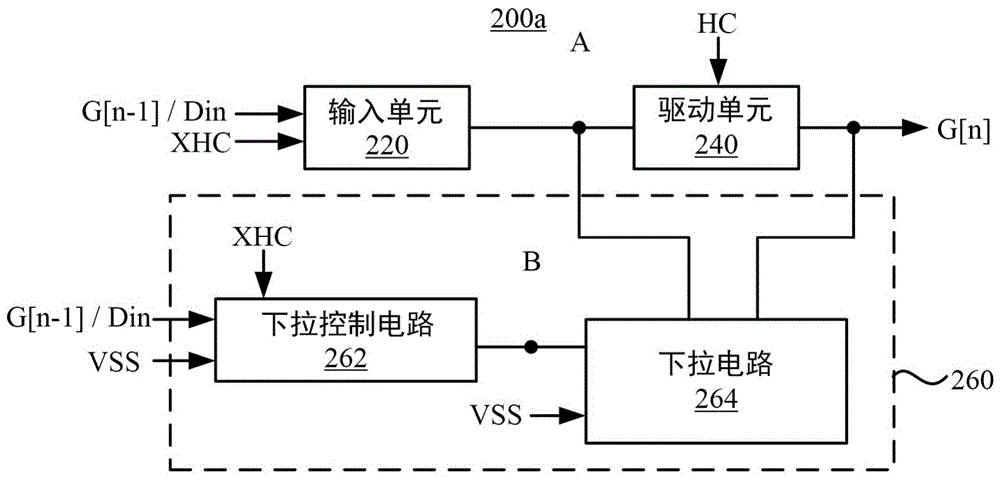
The invention discloses a display panel and a gate driver. The gate driver includes a plurality of driving stages connected in series and outputs a gate driving signal. The driver stage includes an input unit, a driving unit and a pull-down unit. The input unit transmits the gate driving signal of the previous stage to the control node, and the gate driving signal of the previous stage includes a continuous first pulse and a second pulse. The driving unit outputs a gate driving signal according to the level voltage of the control node. The pull-down unit pulls down the gate driving signal to the first voltage after the enabling period of the second pulse. During the enabling period of the first pulse, the input unit pulls up the control node to the second voltage. After the enabling period of the second pulse, the driving unit pulls up the control node to a third voltage, and the third voltage is greater than the second voltage.

Description

technical field [0001] The present invention relates to a display panel (DISPLAY PANEL), in particular to a gate driver of the display panel. Background technique [0002] Recently, various liquid crystal display products have been quite popular. In order to effectively increase the viewing area of ​​the liquid crystal display, display panel technologies suitable for narrow bezels have been continuously proposed. [0003] However, as the resolution of the display continues to increase, the time that the gate driver can drive the display panel to charge becomes shorter and shorter. In order to maintain a certain pixel charging rate, the size of the multiple transistors in the gate driver must increase. In this way, the dynamic power consumption of the gate driver and the layout area of ​​the circuit will be increased, and it is more difficult to apply to the narrow frame application. [0004] Therefore, how to effectively reduce the circuit area of ​​the gate driver and at ...

Claims


Application Information

Patent Timeline
Patent Type & Authority Patents(China)
IPC IPC(8): G09G3/36
Inventor 詹秉燏洪凯尉塗俊达陈勇志
Owner AU OPTRONICS CORP
Learn More