Bicycle for aloft work

A technology for high-altitude work and bicycles, which is applied to overhead lines/cable equipment, etc., can solve the problems of inconvenient operation and movement, difficult speed control, and difficulty in carrying out operations, and achieves the effect of convenient operation, easy operation, and preventing the car body from rolling away.

Active Publication Date: 2014-08-27
STATE GRID CORP OF CHINA +1
View PDF4 Cites 2 Cited by
  • Summary
  • Abstract
  • Description
  • Claims
  • Application Information

AI Technical Summary

Problems solved by technology

However, the body of the operator is on one side of the ground wire, which will inevitably cause the body to tilt, which will bring great inconvenience to the operation and movement, and even cause the danger of "overturning"
So this requires at least two ground personnel to use ropes to tighten the lower end of the gondola at all times to keep it as vertical as possible, but there will still be a certain inclination angle
Moreover, the ground personnel need to choose the location according to the ground conditions. If there are rivers, trees, etc. under the conductor, it will be difficult to carry out the operation.
[0006] Furthermore, the movement of the people-ladder combination depends entirely on the operator to guide the ground wire by hand. In the case of a long distance from the line or a large height difference, the operator consumes a lot of physical strength when going back, and sometimes it is difficult to return when exhausted.
[0007] In addition, the pulley of the hanging basket itself does not have a braking device. When the operator slides down, he basically relies on both hands to hold the wire tightly to brake. The speed is difficult to control and there is danger.

Method used


Image

  • Bicycle for aloft work
  • Bicycle for aloft work
  • Bicycle for aloft work

Examples


Embodiment Construction

[0034] Below in conjunction with accompanying drawing and embodiment the present invention is described in further detail:

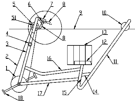
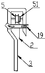
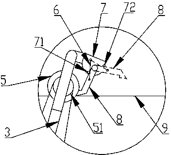
[0035] Aerial work bicycles, such as Figure 1~3 Shown, comprise main beam, seat 12, support forearm 3, support rear arm 11, pedal wheel disc 1, flywheel 51, front roller 5, passive rear roller 10.

[0036] The main beam includes an upper arc beam 16 , a lower straight beam 17 and a vertical beam 15 . The upper arc beam 16 and the lower straight beam 17 are arranged up and down, the upper arc beam 16 is a curved beam with a slight curvature at the front, the lower straight beam 17 is obliquely upward from front to back, the vertical beam 15 is basically vertically arranged, and the vertical beam 15 It is connected to the rear ends of the upper arc beam 16 and the lower straight beam 17. Seat 12 is arranged on the upper end of vertical beam 15, and safety fence 13 is set around seat 12.

[0037] The supporting forearm 3 is connected to the front ends o...


PUM


Abstract

The invention discloses a bicycle for aloft work. The bicycle comprises a main beam. The front side and the rear side of the main beam are correspondingly connected with a front supporting arm and a rear supporting arm. A foot stepping wheel disc is arranged at the joint of the main beam and the front supporting arm. A front hook is arranged at the upper end of the front supporting arm. A front idler wheel which is in chain transmission with the foot stepping wheel disc is arranged in the front hook. A safety handle is arranged in the middle of the front supporting arm. A rear hook is arranged at the upper end of the rear supporting arm. A driven rear idler wheel is arranged in the rear hook. The hook opening of the front hook is provided with a safety lock. The hook opening of the rear hook is provided with a safety lock. A hook body of the front hook is connected with an auxiliary brake device which comprises a connecting plate connected with the hook body, wherein a brake block is hinged to the connecting plate, the two sides of the brake block on the connecting plate are correspondingly provided with a first limiting block and a second limiting block, and a compression spring which keeps the brake block in the first position or the second position is connected between the middle of the brake block and the connecting plate. The bicycle has the advantages of being reasonable in structure, stable in riding and high in safety coefficient.

Description

technical field [0001] The invention relates to an auxiliary tool for power transmission lines, in particular to a high-altitude operation bicycle used on a single power transmission line. Background technique [0002] A lot of work on the high-altitude ground wire of the transmission line, such as replacing the anti-vibration device, installing spacers, repairing the ground wire, etc., can only be completed by going out (sliding along the ground wire to the direction away from the transmission tower). It may be a few meters, a dozen meters, or even tens of meters. [0003] At present, cranes are generally used for outgoing operations. One side of the two ladder rods is provided with an outstretched blue rod for the operator to sit temporarily. The top of the ladder rod is provided with a pulley. The operator uses the hand to pull the ground wire to drive the pulley to slide. Move, so as to drive itself forward or backward. [0004] There are obvious shortcomings in the us...

Claims


Application Information

Patent Timeline
Patent Type & Authority Applications(China)
IPC IPC(8): H02G1/02
Inventor 王申全秦艳军高鹏飞刘伟张道武龚自涛钱俊国刘福祥路永斌任泽宇张昆江佳梁杨军超赵国金
Owner STATE GRID CORP OF CHINA
Why Eureka
Try Eureka