
By-pass switch trigger device of MMC flexible direct-current electronic module

A technology of bypass switch and flexible direct current, applied in the field of bypass switch trigger device, can solve problems such as system tripping and shutdown, bypass switch malfunction, fault expansion, etc., to enhance anti-interference ability, reduce power requirements, and avoid malfunction Effect

Active Publication Date: 2014-08-27
XJ ELECTRIC
View PDF6 Cites 9 Cited by
  • Summary
  • Abstract
  • Description
  • Claims
  • Application Information

AI Technical Summary

Problems solved by technology

Once the bypass switch cannot be reliably closed, the fault will further expand, and the system will eventually be required to trip and shut down
When the controller of the flexible DC sub-module fails to correctly send the closing signal of the bypass switch, whether the bypass switch can operate reliably becomes a difficult problem
[0003] In addition, because the bypass switch needs tens of amperes of current to close, the switch tube of the bypass switch trigger device is relatively large, so the drive circuit can only be integrated on the bypass switch, and then the sub-module controller sends the signal through a long lead wire. The low voltage control signal is transmitted to the control terminal of the bypass switch
However, the existence of long leads makes the bypass switch susceptible to malfunction due to interference from external conditions, causing the number of redundant sub-modules to reach the specified value, which will also cause the system to trip and shut down

Method used


Image

  • By-pass switch trigger device of MMC flexible direct-current electronic module
  • By-pass switch trigger device of MMC flexible direct-current electronic module

Examples


Embodiment Construction

[0017] The present invention will be further introduced below in conjunction with the accompanying drawings and specific embodiments.

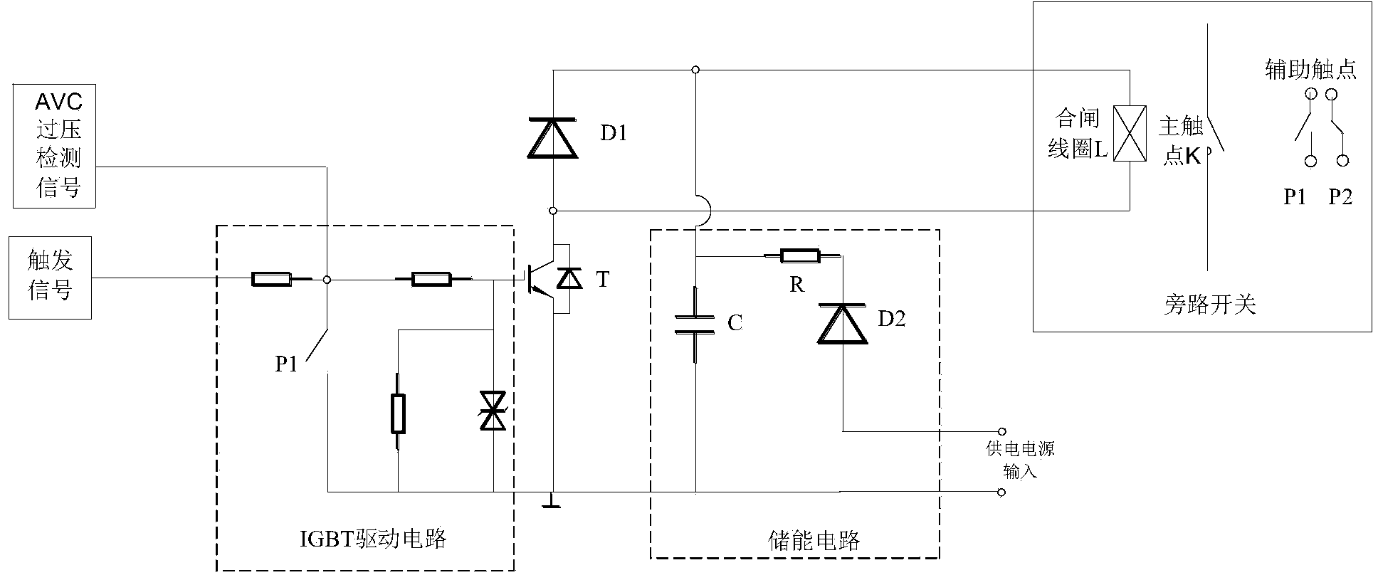
[0018] Such as figure 2 Shown is the circuit principle diagram of the embodiment of the bypass switch trigger device of the MMC flexible direct current transmission electronic module of the present invention. It can be seen from the figure that the device includes an energy storage circuit for connecting with the power supply and a combined The trigger circuit connected to the gate coil L, the energy storage circuit and the trigger circuit are connected to each other; the trigger circuit is connected in series with a switch tube T for controlling the on and off of the trigger circuit, and the control terminal of the switch tube is used to connect to the drive circuit through the switch tube A trigger control switch P1 that is in the same state as the main contact K of the bypass switch is also connected between the trigger signal terminal of ...


PUM


Abstract

The invention discloses a by-pass switch trigger device of an MMC flexible direct-current electronic module. The by-pass switch trigger device comprises an energy storage circuit and a trigger circuit, wherein the energy storage circuit is used for being connected with a power supply, the trigger circuit is used for being connected with a closing coil of a by-pass switch, and the energy storage circuit and the trigger circuit are connected with each other. A switching tube is serially connected in the trigger circuit, a control end of the switching tube is used for driving a trigger signal end of a circuit connection submodule controller through the switching tube, a trigger control switch is connected between the control end of the switching tube and the ground, and the state of a main contact of the trigger control switch is consistent with the state of a main contact of the by-pass switch. By means of the by-pass switch trigger device, a control end of the switching tube driving circuit is connected with the trigger control switch and used for switching off the switching tube after the by-pass switch is switched on, so that a power requirement on the switching tube is reduced, and the size is decreased. The trigger device is integrated in the submodule controller, therefore, malfunction caused by interference of lower-pressure control signals of the switching tube when the lower-pressure control signals of the switching tube are connected through long leads is avoided, and capacity of resisting interference is improved.

Description

technical field [0001] The invention belongs to the field of flexible direct current transmission, and in particular relates to a trigger device for a bypass switch of an MMC flexible direct current transmission electronic module. Background technique [0002] Each bridge arm of the MMC flexible direct current transmission converter valve usually consists of hundreds of such as figure 1 The MMC flexible direct current transmission sub-modules shown are connected in series. When a sub-module fails, the faulty sub-module must be removed quickly through the bypass switch K to keep the system running. Once the bypass switch cannot be reliably closed, the fault will further expand, and the system will eventually be required to trip and shut down. When the controller of the flexible DC sub-module fails to correctly send the closing signal of the bypass switch, whether the bypass switch can operate reliably becomes a difficult problem. [0003] In addition, because the bypass swi...

Claims


Application Information

Patent Timeline
IPC IPC(8): H02M1/08
Inventor 张建夏克鹏刘刚范彩云姚钊
Owner XJ ELECTRIC
Features
  • Generate Ideas
  • Intellectual Property
  • Life Sciences
  • Materials
  • Tech Scout
  • Unparalleled Data Quality
  • Higher Quality Content
  • 60% Fewer Hallucinations
Learn More