OTDR optical path detection device and method thereof

A technology of optical path detection and optical fiber link, which is applied in the field of optical communication, can solve the problems of high price, high maintenance personnel skill requirements, complex test networking scheme, etc., and achieve the effect of reducing complexity and cost

Inactive Publication Date: 2014-08-27
ZTE CORP
View PDF8 Cites 12 Cited by
  • Summary
  • Abstract
  • Description
  • Claims
  • Application Information

AI Technical Summary

Problems solved by technology

The traditional external OTDR instrument is expensive and bulky, and the optical fiber needs to be disconnected from the system to analyze the fault or the location of the breakpoint before detection. It cannot detect the optical fiber link in real time, which affects the normal operation of the service light. transmission
In addition, the test networking scheme of the external OTDR instrument is complicated, and the technical requirements for maintenance personnel are also relatively high

Method used


Image

  • OTDR optical path detection device and method thereof
  • OTDR optical path detection device and method thereof
  • OTDR optical path detection device and method thereof

Examples


Embodiment Construction
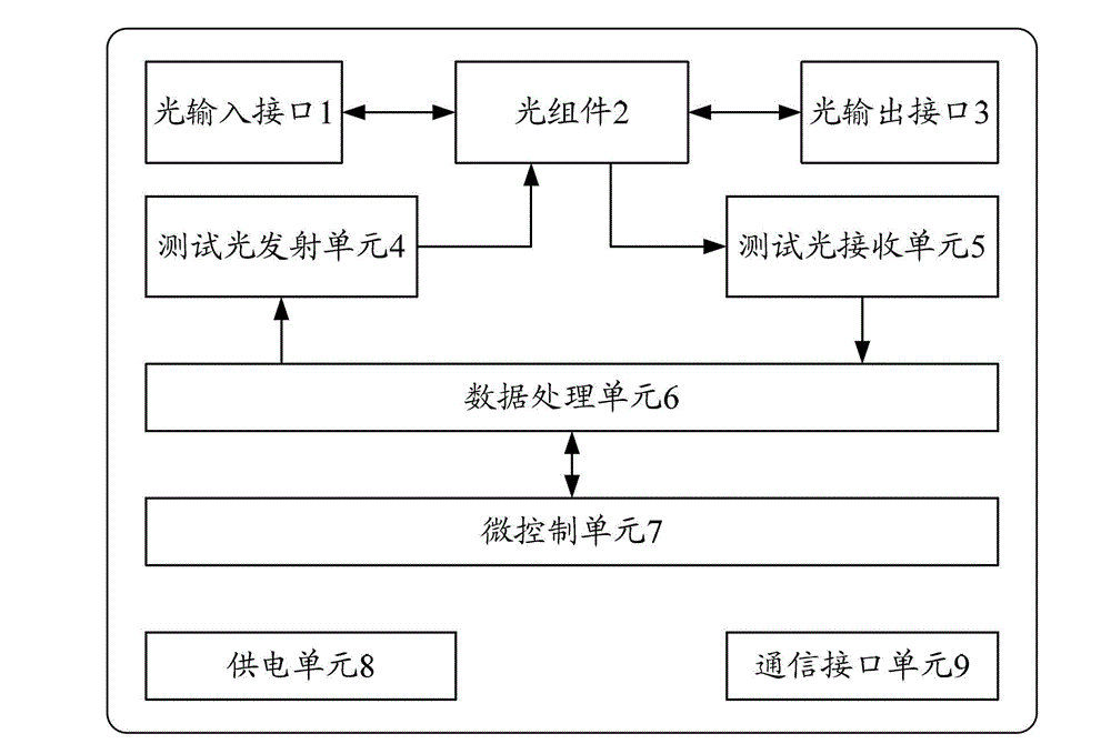
[0043] The main idea of ​​the solution in the embodiment of the present invention is to combine OTDR technology with optical transmission equipment to form an optical transceiver integrated device dedicated to OTDR optical path detection, which integrates the detection light emission function, scattered light and reflected light reception function, detection data processing function, As well as the unit control function, this technology will replace the existing external OTDR instrument solution, and try to retain the measurement accuracy of the original technology as much as possible, while overcoming the shortcomings of the external OTDR instrument. It only needs to add an OTDR optical path detection device dedicated to OTDR optical path detection on the outside of the original optical transmission equipment to complete the real-time detection of optical fiber links, so as to realize efficient detection and maintenance of massive optical fibers.

[0044] Such as figure 1 As ...


PUM


Abstract

The invention relates to an OTDR optical path detection device and a method thereof. The device comprises an optical input interface, an optical output interface, a detection light emission unit, an optical assembly, a detection light receiving unit, a data processing unit, a micro-control unit, a power supply unit and a communication interface unit. According to the invention, a detection light emission function, a diffusion light and reflected light receiving function, a detection data processing function and a unit control function are integrated. The light transmit-receive integrated device is embedded in an optical network to be measured. Then, the optical network to be measured can be detected at real time, and normal service light transmission is not influenced. Thus, a special OTDR instrument for and fiber optics detection and a matching testing device are eliminated; a step of fiber fault detection is simplified; and complexity and cost of optical network maintenance are reduced.

Description

technical field [0001] The present invention relates to the technical field of optical communication, in particular to an OTDR optical path detection device and method with the function of an optical time domain reflectometer (OTDR, optical time domain reflectometer). Background technique [0002] In optical fiber communication, the transmission medium - optical fiber will inevitably have link failures, which will affect the transmission of optical signals. In order to accurately locate the location of the fault, it is necessary to use a special optical time domain reflectometer to detect and locate the fault. [0003] OTDR is realized based on Rayleigh scattering and Fresnel reflection when light is transmitted in the optical fiber. Its working principle is to send a short pulse of light into the optical fiber. When the pulsed light is transmitted in the optical fiber, due to the Characteristics, connection points, junctions, etc., the pulsed light will produce scattering ...

Claims


Application Information

Patent Timeline
Patent Type & Authority Applications(China)
IPC IPC(8): H04B10/071
CPCH04B10/071H04B10/0771H04B10/0773
Inventor 陈雷付志明匡国华贝劲松李锟余辰东
Owner ZTE CORP
Why Eureka
Try Eureka