
Transverse-Electromagnetic (Tem) Radio-Frequency Coil For Magnetic Resonance

一种射频线圈、横向电磁的技术,应用在横向电磁(TEM)射频(RF)线圈,磁共振(MR)系统领域,能够解决不提供可靠的基础、供应或供给有问题、很难等问题,达到灵敏度减少、RF功率减少、减少SAR的效果

Active Publication Date: 2014-08-27
KONINKLJIJKE PHILIPS NV
View PDF4 Cites 5 Cited by
  • Summary
  • Abstract
  • Description
  • Claims
  • Application Information

AI Technical Summary

Problems solved by technology

However, supply or supply of RF power is problematic in QBC based MR systems when the birdcage coil is floating about RF ground due to thermal RF connections
Moreover, the problem does not provide a reliable basis for EM simulations of such devices
Especially in the case of degenerate birdcage coils, RF cable connections are difficult to define and dictate by the patient in the MR system Simulation of the management of the Specific Absorption Rate (SAR) with respect to RF energy

Method used


Image

  • Transverse-Electromagnetic (Tem) Radio-Frequency Coil For Magnetic Resonance
  • Transverse-Electromagnetic (Tem) Radio-Frequency Coil For Magnetic Resonance
  • Transverse-Electromagnetic (Tem) Radio-Frequency Coil For Magnetic Resonance

Examples


Embodiment Construction

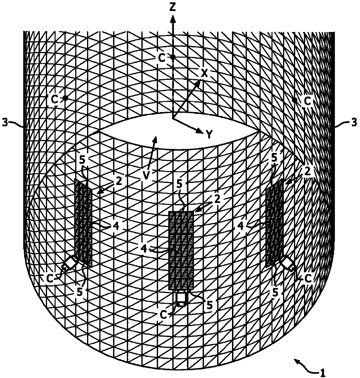
[0039] figure 1 A conventional transverse electromagnetic (TEM) radio frequency (RF) coil 1 for a magnetic resonance system such as an MRI system is shown C . Conventional TEM Coil 1 C Comprising a plurality of TEM coil elements 2 functioning as coil 1 C The RF grounded cylindrical screen form is arranged inside and surrounded by the RF enclosure 3 . The central axis of the cylindrical RF screen 3 corresponds to the coil 1 C the z-axis, as in figure 1 Indicated by Cartesian coordinates shown in . Each of the plurality of TEM coil elements 2 includes an elongated coil strip section 4, and the TEM coil elements 2 are arranged such that the strip sections 4 are substantially adjacent to each other at fixed intervals around the z-axis within the RF screen 3. parallel and spaced apart. Since the RF screen 3 in this example is cylindrical, all strip-like sections 4 of the TEM coil element 2 are away from the coil 1 C The z-axis basically has the same radius pitch. In this e...


PUM


Abstract

The present invention provides a transverse-electromagnetic (TEM) radio-frequency coil (1) for a magnetic resonance system, especially for a magnetic resonance imaging system. In particular, the inventive concept provides a coil (1) in which at least one of the opposite end regions of the elongate strip section (4) of each TEM coil element (2) has a lateral extension (6) transverse to a longitudinal extent of the strip section (4). These lateral extensions (6) combine with strip sections (4) to form L-or U-shaped TEM coil elements (2) and provide ‘ring-like’ current contributions resulting in a reduction of the z-sensitivity compared with a conventional TEM coil. The result is a coil array having TEM coil elements (2) that provide smaller sensitivity profiles in the z-direction, yet preserve the characteristics of a well-defined RF ground, e.g. via an RF shield or screen (3). The reduced field of view in z-direction not only reduces noise reception but also reduces the SAR generated in those regions during transmission.

Description

technical field [0001] The present invention relates to the field of magnetic resonance (MR), and more particularly to transverse electromagnetic (TEM) radio frequency (RF) coils for use in MR applications, and to magnetic resonance (MR) systems incorporating such coils. Background technique [0002] MR systems, and in particular magnetic resonance imaging (MRI) systems, frequently employ quadrature birdcage coils (QBC) which, compared to TEM coils, are larger in the z direction (ie, In the axial direction) has the advantage of a shorter field of view (FOV), while providing a higher signal-to-noise ratio (SNR), and also has a lower overall RF power requirement. However, supply or delivery of RF power in QBC based MR systems is problematic when the birdcage coil is floating about RF ground due to thermal RF connections. Furthermore, the problem does not provide a reliable basis for EM simulations of such devices. Especially in the case of degenerate birdcage coils, the RF c...

Claims


Application Information

Patent Timeline
Patent Type & Authority Applications(China)
IPC IPC(8): G01R33/34G01R33/345
CPCG01R33/34092G01R33/34046G01R33/3453G01R33/3456
Inventor C·洛斯勒D·维尔茨
Owner KONINKLJIJKE PHILIPS NV
Learn More