Pull rod press machine with power arranged at lower portion

A technology of presses and tie rods, applied in presses, stamping machines, manufacturing tools, etc., can solve the problems of poor mechanical properties of presses, ineffective hydraulic cylinder speed-up, large overall size of presses, etc., to meet the requirements of strength and Rigidity requirements, superior comprehensive performance, and high energy utilization

Active Publication Date: 2014-09-03
苏州市东望医疗设备有限公司
View PDF9 Cites 6 Cited by
  • Summary
  • Abstract
  • Description
  • Claims
  • Application Information

AI Technical Summary

Problems solved by technology

[0003] At present, the mechanical press widely used in China has the advantages of fast speed and high efficiency. However, since it is usually equipped with a flywheel and the power system is placed above the workbench, the asymmetry of the flywheel structure and the upper placement of the power system will lead to The center of gravity of the press is relatively high, resulting in poor mechanical properties and stability of the press, and low energy utilization rate, large structural size, and relatively bulky appearance
In addition, the impact force of the press on the worktable is relatively large, so that the base bears a large impact force, and the vibration and noise are relatively large. At the same time, the base of the press needs to have high strength and rigidity. Therefore, in a certain To a certain extent, the overall size of the press is too large
[0004] However, although the widely used hydraulic presses are small in size and high in control precision, they are slow in speed and small in working strokes, resulting in low production efficiency, difficult system maintenance, easy oil leakage, and high maintenance costs.
In addition, the oil of the traditional hydraulic press achieves speed-up through the external differential circuit, but the pressure loss of the oil in the external differential circuit is relatively large, which leads to the ineffective speed-up effect of the hydraulic cylinder and increases the number of pipelines. and connection costs

Method used


Image

  • Pull rod press machine with power arranged at lower portion
  • Pull rod press machine with power arranged at lower portion
  • Pull rod press machine with power arranged at lower portion

Examples


Embodiment Construction

[0018] The technical solutions of the present invention will be further described below in conjunction with the accompanying drawings and specific implementation methods.

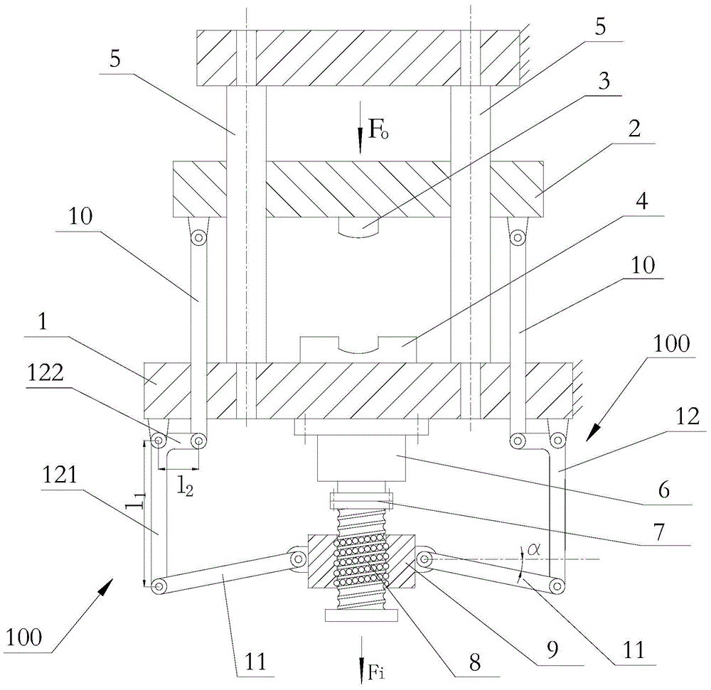
[0019] see figure 1 The shown press includes a workbench 1 fixedly arranged on the frame, an upper mold assembly 2 that is vertically lifted and lowered on the frame and positioned above the workbench 1, and the upper mold assembly 2 includes an upper and lower The sliding seat 2 that is lifted and lowered on the frame, the upper mold 3 that is fixedly arranged under the sliding seat 2, the lower mold 4 that matches the upper mold 3 is fixedly arranged on the workbench 1, and the upper mold 4 is installed on the workbench 1. There are a plurality of vertically extending guide posts 5 to provide guidance for the sliding seat 2 to slide up and down.

[0020] The press also includes a motor 6 fixedly installed under the workbench 1 , a lead screw 8 connected to the output shaft of the motor 6 , and a nut 9 sl...


PUM


Abstract

The invention discloses a pull rod press machine with power arranged at the lower portion. A motor, a screw and a nut are combined as a power system and arranged under a work table. Force-amplifying mechanisms are arranged between an upper die assembly and the nut so that the upper mold assembly can output large output force, and forming and machining of work-pieces are convenient. Under the condition of needing certain tonnage of the press machine, the low-power motor can be adopted, so that the energy is saved and the cost is lowered. Meanwhile, due to the fact that the power system is arranged at the lower portion, the stress state of a base under the work table is improved, the base of the press machine can meet the strength and rigidity requirements more easily, shock absorption and noise reduction are facilitated, and the gravity center of the press machine descends, so that the dynamic property of the press machine is improved. Compared with a structure in the prior art, the structure size of the press machine is greatly reduced, the impact force is large, the work efficiency is high, the energy utilization rate is high, the work noise is low, and excellent combination property is achieved.

Description

technical field [0001] The invention relates to a dynamic lower-mounted tie rod press. Background technique [0002] In the field of forming processing, mechanical presses and hydraulic presses are two main processing equipments, which are used for punching, bending, stretching, extrusion and other processing of products. [0003] At present, the mechanical press widely used in China has the advantages of fast speed and high efficiency. However, since it is usually equipped with a flywheel and the power system is placed above the workbench, the asymmetry of the flywheel structure and the upper placement of the power system will lead to The center of gravity of the press is relatively high, resulting in poor mechanical properties and stability of the press, low energy utilization, large structural size, and relatively bulky appearance. In addition, the impact force of the press on the worktable is relatively large, so that the base bears a large impact force, and the vibrati...

Claims


Application Information

Patent Timeline
Patent Type & Authority Applications(China)
IPC IPC(8): B30B1/10
Inventor 王明娣汤攀飞王金娥
Owner 苏州市东望医疗设备有限公司
Why Eureka
Try Eureka